Description
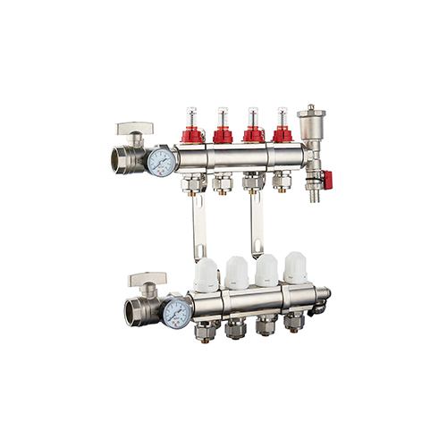 |
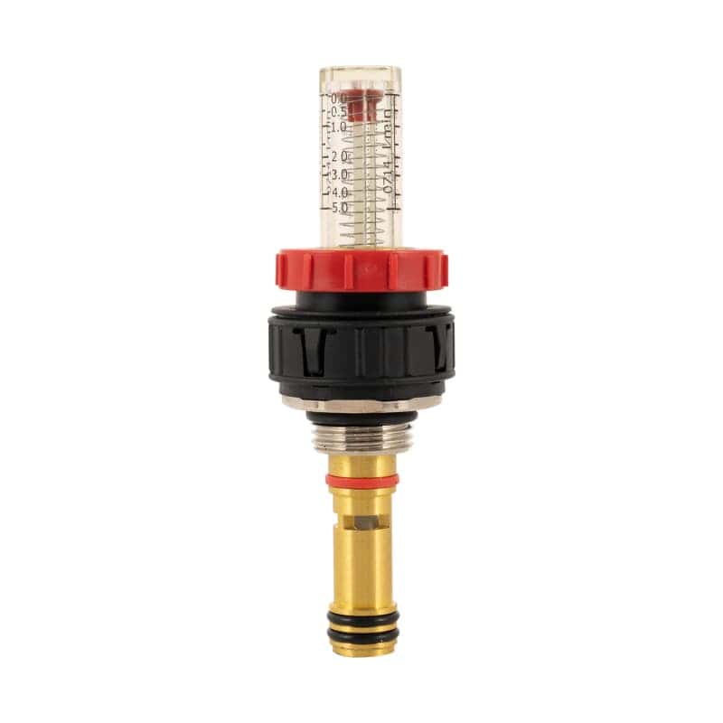
Brass Underfloor Heating Manifold With Ball Valve
Brass Underfloor Heating Manifold with Ball Valve: The integrated ball valve enables fast on-off control of each branch circuit. It is used to collect and shunt the hot water delivered by a boiler or a heat pump in a radiant floor heating system. By adjusting the opening degree of each branch ball valve with flow control, the flow is accurately distributed to each floor heating circuit pipeline, ensuring that the indoor temperature in different areas meets the design requirements.
|
|
|
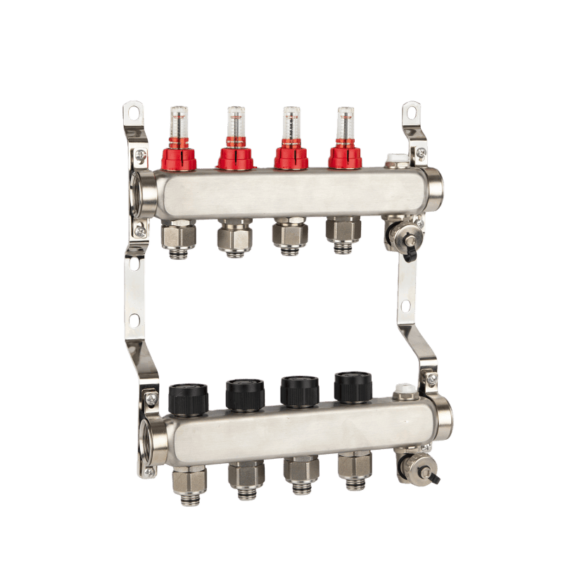
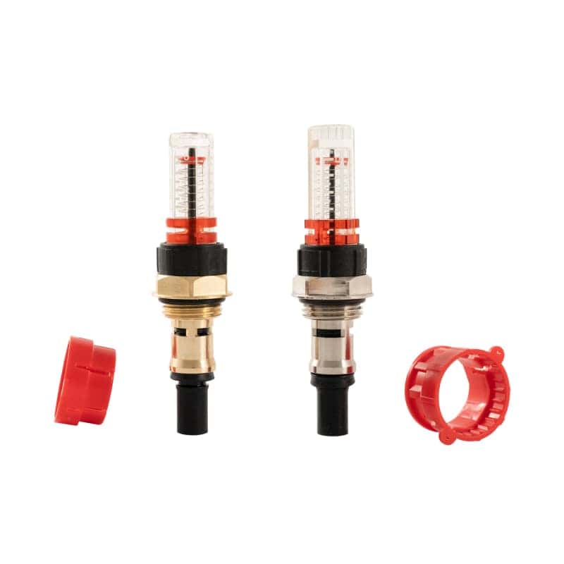
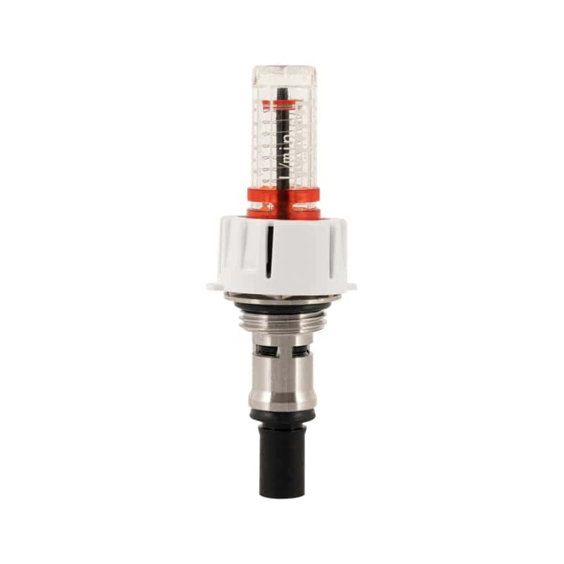
Stainless Steel Distribution Manifold
The stainless steel distribution manifold is suitable for a variety of fluid media and complex working environments. It is used in heating, water supply, industrial fluid transmission systems, etc., to uniformly distribute or converge the centralized transmission fluid (such as hot water, cold water, industrial media, etc.), accurately distribute it to each branch pipe, and facilitate individual control, flow regulation, and maintenance of each branch.
|
|
|
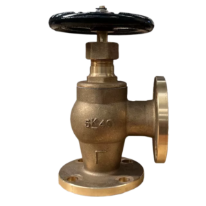
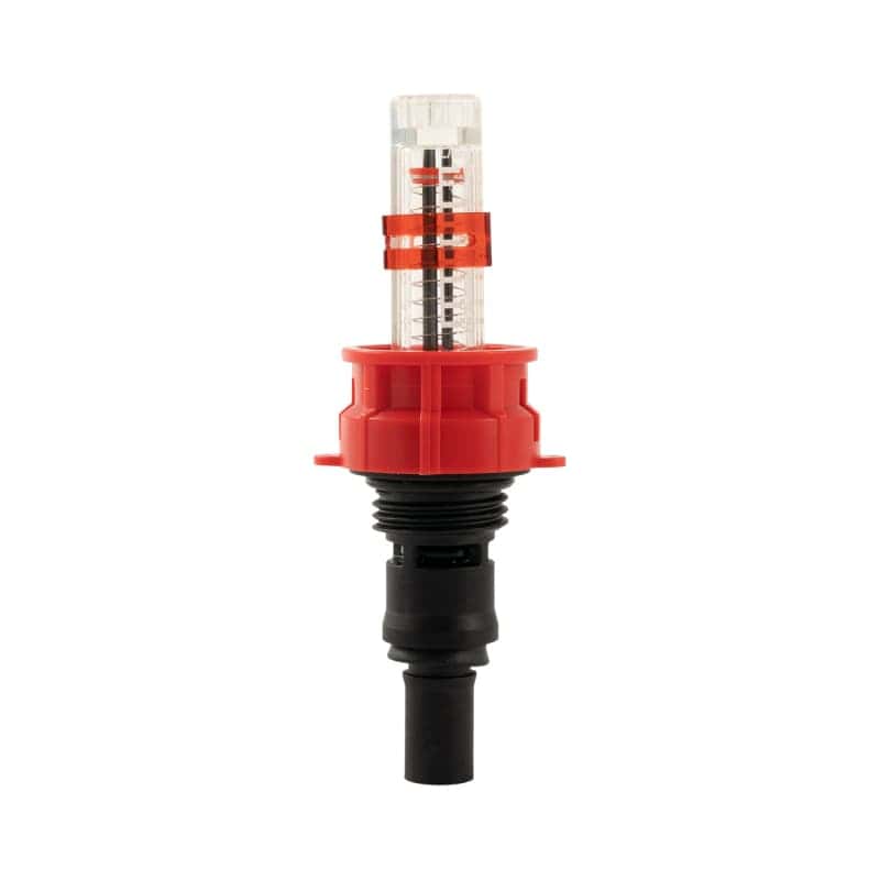
Heating Distributor
The Heating Distributor is the core fluid distribution and control device in the heating system, which adapts to the hot water medium and working environment of the heating system. It is used to collect the hot water from the boiler, heat pump, and other heat source equipment and distribute it evenly to each heating branch indoors. At the same time, it can accurately control the hot water flow of each branch through the matching valve or flow regulator.
|
 |
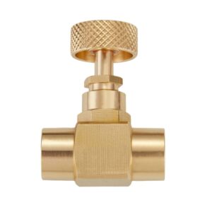
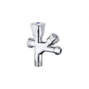
Steel Boiler Manifold Garden Hose 2-Way Splitter is a garden water supply accessory installed at the outdoor faucet or faucet interface. Its function is to divide a single inlet into two independent outlets, and each outlet is typically equipped with an independent switch to control the water flow separately. It is primarily used to meet the multi-channel water supply needs of gardens, courtyards, and other outdoor areas.
|
|
|
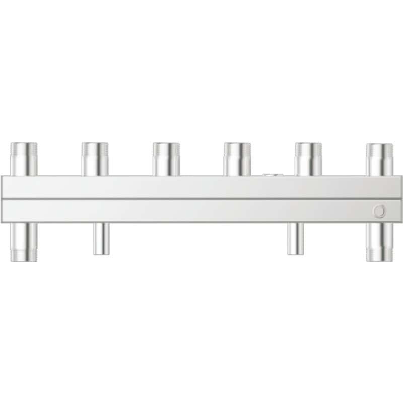
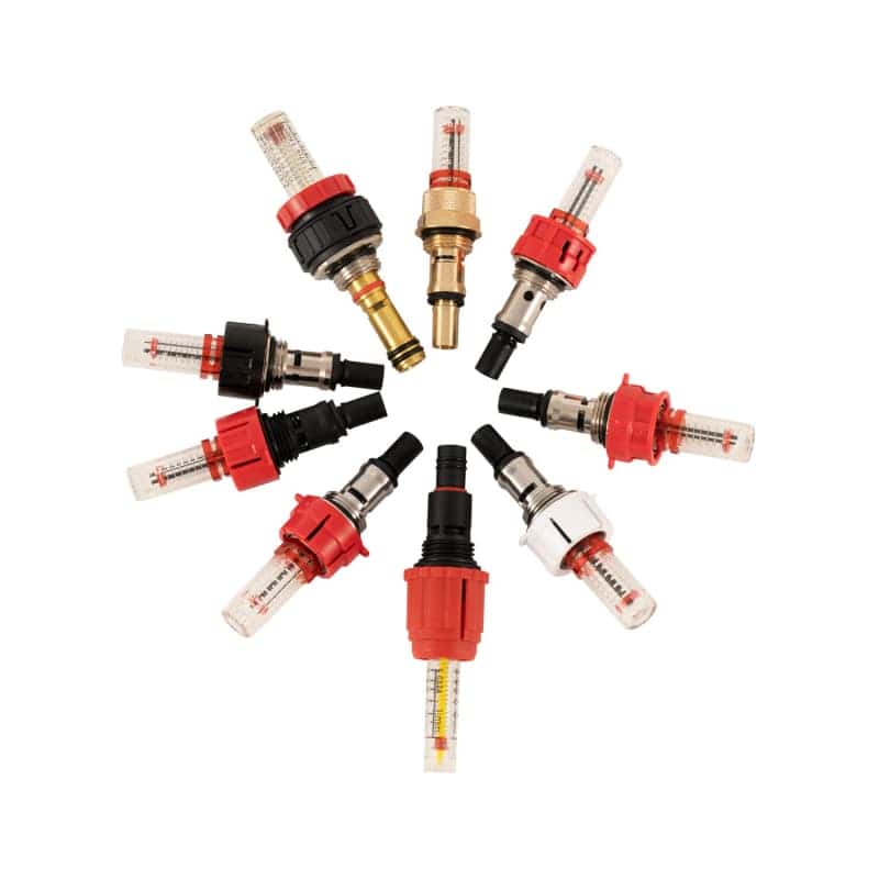
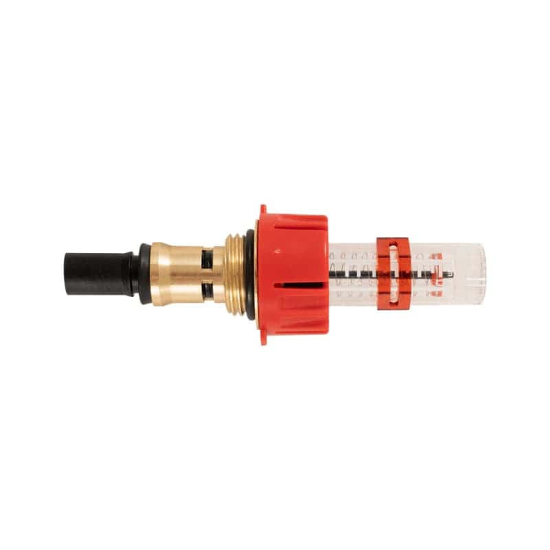
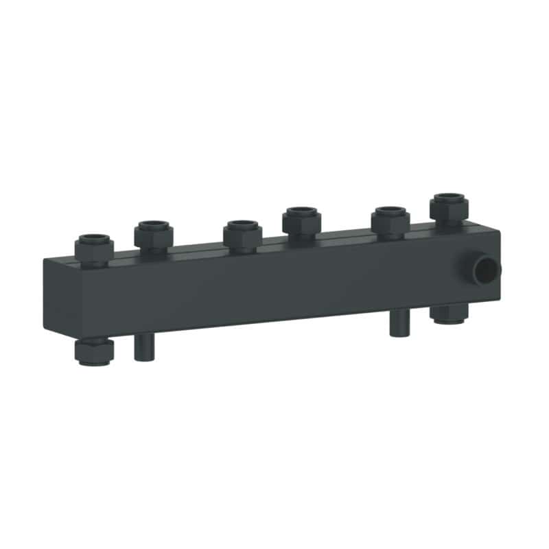
Hydraulic Balance Manifold
The Hydraulic Balance Manifold is a core regulating device specially designed for a fluid system. It is usually composed of the main pipe body, multi-branch interface, flow balance valve, and monitoring component. Stainless steel or brass is mostly selected to adapt to the working environment of the heating and water supply system. Its core function is to realize the hydraulic balance of each branch in the system and solve the problem of excessive or too small flow in some areas caused by uneven fluid distribution.
|
|
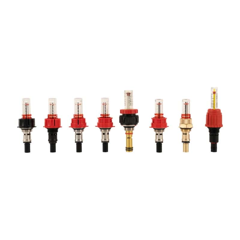
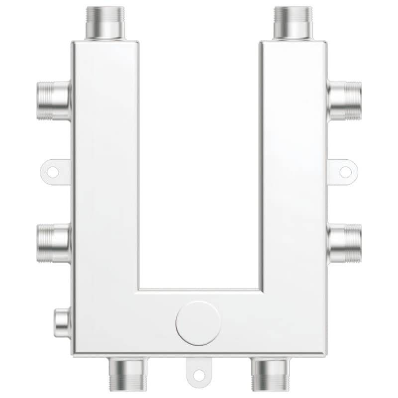
Annular Hydraulic Distributor
Annular Hydraulic Distributor is a fluid distribution and regulation device with an annular structure design and corrosion-resistant materials such as stainless steel. The annular structure can realize 360° uniform flow distribution of fluid, adapt to complex pipeline layout, quickly and evenly distribute the centralized input fluid to each branch pipeline in heating, water supply, industrial fluid transmission, and other systems, and accurately control the flow and pressure of each branch through matching adjustment components.
|