What Is a Valve Actuator?
A valve actuator is a device used to operate a valve by moving every part of the valve in response to a control signal. These components may include the plug, the gate, or the ball. It is a motorized system that can automatically or remotely open or close a valve in its most basic form.
There are several distinct kinds of valve actuators, each of which can be operated uniquely. These actuators can be manually operated, pneumatically operated, hydraulically operated, or electrically operated. Some actuators are more suitable for rotary motion, while others are better suited for linear motion.
What is the Electric Valve Actuator?
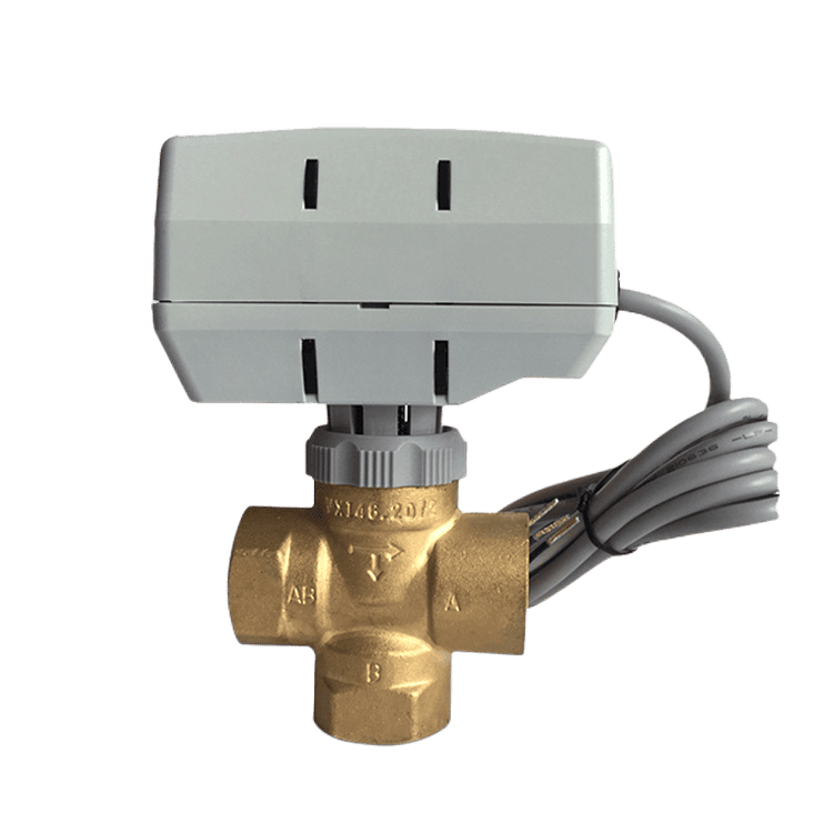
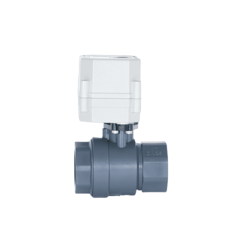
Electric valve actuators control the opening and closing of valves. They may offer rotary or linear motion and are compatible with various valve types, including butterfly and ball valves. Electric valve actuators respond to signals from remote or centralized process control systems, making them essential for managing complex, difficult-to-reach, or distributed systems.
Process management systems can control electric actuators from a centralized system that provides planned and programmed commands, enabling firms to streamline their systems and increase their reliability. It comprises an electric motor, a gearbox, and various control components. The motor generates rotational motion, which is transmitted to the valve through the gearbox. The gearbox provides torque amplification and reduction, enabling efficient operation of the valves.
Electric Valve Actuator: How Does it Work?
The working principle of an electric valve actuator involves the following main components.
- Electric Motor: The actuator is equipped with an electric motor that changes electrical energy into mechanical rotational motion. The motor is typically a brushless DC motor or an AC motor.
- Gear Mechanism: The rotational motion of the electric motor is transmitted to a gear mechanism, which converts the high-speed rotation of the motor into a lower-speed, higher-torque output. This gear mechanism provides the necessary power to actuate the valve.
- Output Shaft: The actuator’s output shaft is connected to the valve stem or actuator mount. As the motor rotates the output shaft, it transfers the motion to the valve, causing it to open or close, depending on the required operation.
- Limit Switches: Electric valve actuators often incorporate limit switches. These switches are positioned to detect the valve’s fully open and closed positions. When the valve reaches these positions, the limit switches send signals to the actuator control system, indicating the valve’s status.
- Control System: The actuator’s control system receives signals from an external control source, such as a Programmable Logic Controller or a control panel. These signals dictate the valve’s desired position or degree of opening/closing. The control system then processes these signals and sends appropriate commands to the electric motor, driving the actuator in the required direction.
- Feedback Mechanism: Electric valve actuators often employ feedback to ensure accurate valve positioning. This mechanism consists of position sensors, such as potentiometers or encoders, that provide continuous feedback on the valve’s actual position. The control system compares this feedback with the desired position and adjusts the motor’s operation accordingly to achieve precise control over the valve position.
Electric Valve Actuators: Main Types
Rotary Electric Valve Actuators

Actuators for electric rotary valves rotate components using electromagnetic power from a motor. Frequently, they provide control and indexing capabilities to permit multiple pauses at multiple positions along strokes. Rotary electric valve actuators comprise an electrical motor, an electric enclosure, reduction gearing, a drive coupling between the valve stem and the final drive gear, and travel-limiting devices. Either a circular shaft or a table may serve as the rotational element. Keyways are a common feature of circular shafts.
• Actuator torque – Actuator torque, the force that turns the axis, is calculated by multiplying the applied force by the distance between the pivot point and the end at which the force is given.
• Motion range – The complete motion range can be
- 90° (quarter-turn)
- 180° (nominal)
- 270° (nominal)
- 360° (multi-turn).
Linear Electric Valve Actuators

Linear electric valve actuators feature a motor-driven ball screw or ACME screw system, enabling linear movement. Most of the time, ACME screws can hold loads without power, but they are generally not as good as ball screws. Ball screws are power screws featuring a train of ball bearings that move back and forth, riding between the screw and the nut. They are more efficient and have less friction than lead screws. With linear electric valve actuators, the load is not supported and connected to the end of a screw or rod. Most of the time, a belt or gear drives the screw. The linear electric actuator will have an electrical enclosure, an electric motor, reduction gears, a valve stem drive nut or bushing, and devices that limit the actuator’s movement.
Linear electric valve actuators have the following specifications:
• Valve stem stroke length
Measure the length of a stroke in inches. The duration that a valve has to move from fully open to fully closed is called its “stroke.” If you use an actuator with fewer strokes than the valve, you will “short stroke” the valve and not get the full CV rate of the valve.
• Seating Thrust or Actuating Force
pounds (lbs) are used to measure the force of an actuator. The actuator must have sufficient force to overcome the pressure in the design, allowing the closing element to close and remain closed.
• The number of turns
The number of turns that a multi-turn actuator makes as the valve stem moves from the completely closed position to the fully open one.
What are the Benefits of Using an Electric Valve Actuator?
The ability to operate electrically actuated valves remotely is one of their primary advantages. This reduces the need for manual labor and enhances operational efficiency. They also offer greater precision than manual valves, resulting in improved control and accuracy.
What are the Applications of an Electric Valve Actuator?
To remotely control ball and butterfly valves, electric quarter-turn actuators are used. They significantly simplify the operation of quarter-turn valves by providing remote, automated control. Additionally, they provide sufficient torque for valves that require higher torques than a human can produce. These actuators are utilized in heating systems, manufacturing automation, water supply, irrigation, fluid metering, and transportation or transfer of fluids.
What Is the Temperature Range of the Electric Actuator Valve?
Electric actuators have a temperature range of -40 to 150°F (- -40 to 65°C). When used outdoors, an electric actuator must be closed tightly to prevent moisture from entering the internal mechanisms. If drawn from the power supply conduit, which may have captured rainwater before installation, condensation may still form inside. Also, since motors warm the interior of the actuator enclosure when operating and cool it when not, temperature fluctuations may result in “breathing” and condensation in the environment. Therefore, all outdoor electric actuators should be equipped with a heater.
What are the Features of Electric Valve Actuators?
Position indicators
Position indicators denote the current open or closed position of the actuator. Electric position feedback systems also convey the position to your design (i.e., the controller). There are two fundamental switching options for position indicators: mechanical switches and proximity (non-contact) switches. Internal cams on the output drive shaft activate mechanical limit valves. Limit switches can also serve as automatic controls. Position-detection sensors activate proximity switches that detect valve position. Position indicators may display only the fundamental on and off states, or they may also indicate partially open or closed conditions.
Manual override

Manual override is a safety feature found in most actuators. Generally, it is a mechanical handwheel or handle. This wheel lets you manually close or open a valve during a power outage or other emergency.
Limit switches
Limit switches are an electromechanical actuator component. A closed-limit switch cam and an open-limit switch are included. The associated switch can also act as the actuator, driving a valve to the open or closed position. When a position is attained, the corresponding switch cam cuts power. Consequently, it prevents further movement and limits accommodation. Limit seating is the maintenance of a valve’s terminal position. The limit switch shafts of particular actuators are adjustable. This lets you specify an end position, such as 75% open. Position indicators can integrate limit switch cams as a mechanical link between the valve and the actuator.
Fail-safe
A vital safety feature of some automated valve actuators is a fail-safe mechanism. The failsafe is designed to close or open a valve in the event of a power interruption. Such a system requires an energy storage mechanism, such as an actuator or a battery. The fail-safe mechanism will typically close the valve. A loaded spring in a spring mechanism automatically closes the valve when the power is interrupted. For a backup battery system, also known as a battery safety return (BSR), the actuator is powered by a battery.
Depending on the battery’s capability and the actuator’s performance, the charging time and total number of turns will vary. Specific actuators will implement both fail-safe versions for added redundancy in their design. As stated, most fail-safe operations will close the valve during a power outage; however, specific applications require the valve to remain open. For example, consider the cold water flow into a heat exchanger. Cold water would be needed to cool any excess warming fluid to prevent overheating.
Duty cycle
The duty cycle specifies the duration for which an actuator is used between processes. The opening and closure of the valve constitute one cycle. The duty cycle is the percentage ratio of on-time to off-time. It is calculated using the following formula. If an actuator requires 10 seconds to open, 20 seconds to close, and 30 seconds to rest after opening and closing, the duty cycle would be (10 + 20)/(10 + 20 + 30) = 50%.
Duty cycle = (opening time + closing time) / (opening time + closing time+ rest) multiply by 100: duty cycle
Modulation
Some electric valve actuators, also known as DPS (digital positioning system), can modulate control. This is the ability to precisely position the valve at any angle between completely open and fully closed (0° to 90°). This is required for applications requiring a variable discharge rate. Modulation is typically accomplished with a control loop system and a positioning circuit board (PCB) inserted in the actuator.
Electric Valve for Actuator: Selection Criteria
Electric actuators are devices commonly used in various industrial applications, including water treatment plants, chemical processing facilities, electricity generation, oil refineries, and other sectors. These electric actuators are mechanical and electronic components combined into a single device. To select the best electric actuators, consider the following eight factors.
Operating Torque
The operating torque is the most significant factor when choosing an electric actuator for a valve. The electric actuator output torque should be 1.2 to 1.5 times higher than the maximum torque the valve action can generate.
Thrust of Operations
The mainframe structure of the electric valve device can be either one of two distinct types: the first type does not have a thrust disk. Therefore, its output torque is generated directly. The other one is set up with a thrust disk, and the output torque is transformed into output thrust through the stem nut contained within the thrust disk.
Stem Diameter
It is not possible to assemble an electric valve out of a multi-turn type rising stem valve if the electric device permits the maximum stem diameter to pass through the stem of the matched valve. This prevents the electric valve from being assembled.
Therefore, the inner diameter of the output shaft for the electric actuator must be larger than the outer diameter of the valve stem for it to function properly. Although you are not required to consider the stem diameter when using a rotary valve or a multi-turn valve in a non-rising stem valve, it is suggested to do so during the matching process. This will ensure that the assembly operates efficiently.
Output Speed
There is a potential for a water strike if the valve’s opening and closing speeds are too fast. Therefore, selecting an appropriate opening and closing speed is vital after considering the various conditions.
Motor
The control torque of the motor is not determined until after all of its specifications have been determined. When operating within the set time limit, the motor will not exceed its load capacity.
Power Voltage
AC220V, AC380V, and DC24V are voltages for the general electric actuator.
Control Model
The electric actuator for the valve can be either a switching type or a regulating type. The regulating type of actuator signal can likewise be either a current signal or a voltage signal.

Maintenance and Troubleshooting Tips for Electric Valve Actuators
Electric valve actuators must be appropriately maintained to operate effectively and regularly. Cleaning and lubricating the actuator’s parts, inspecting for wear and tear, and testing the actuator’s operation are all part of routine maintenance.
It’s crucial to locate the source of the issue when fixing electric valve actuators. The control unit, gearbox, and motor failures are frequent issues with electric valve actuators. The proper repair or replacement can be made once the problem has been identified and assessed.