“Floor Heating Mixed Water Center For Water Temperature Control System” has been added to your cart. View cart
Tri Clamp Manifold
Parameters of Tri Clamp Manifold
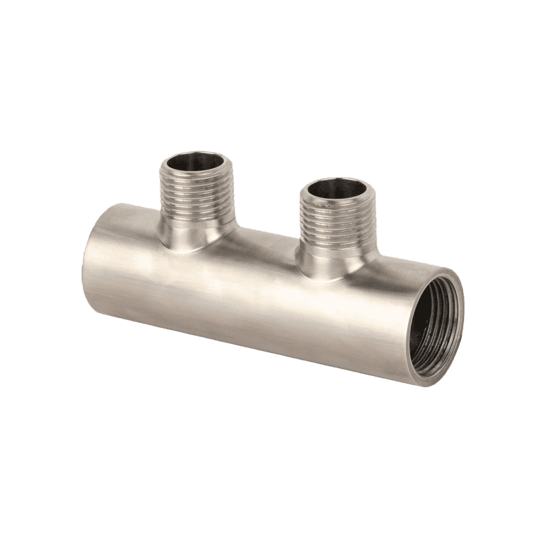
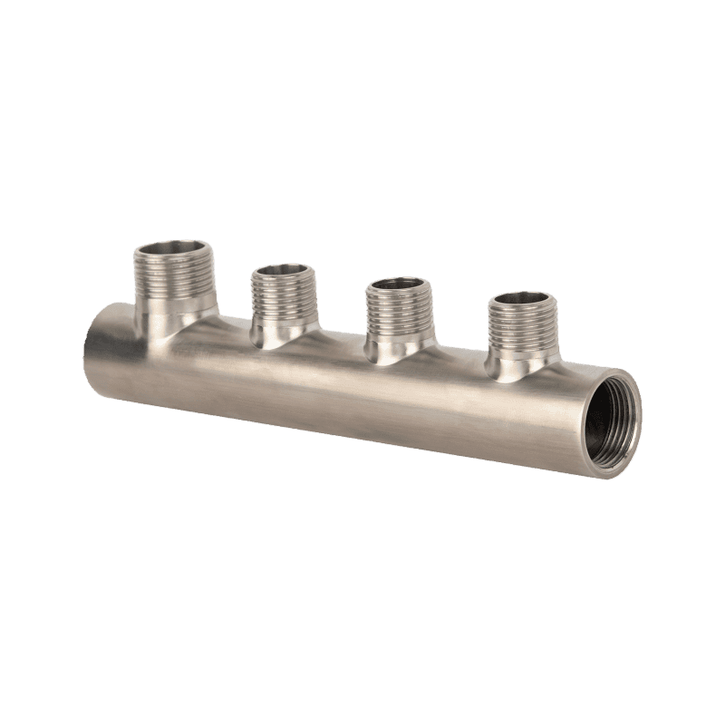
Tri Clamp Stainless Steel Manifold
This tri-clamp stainless steel manifold is made from stainless steel and uses clamp-type quick connections. It is available in different models with 2 to 6 branch ports. The clamp design allows fast, tool-free installation and removal. It splits one main fluid line into multiple branches and works with clean fluid pipelines of various sizes.
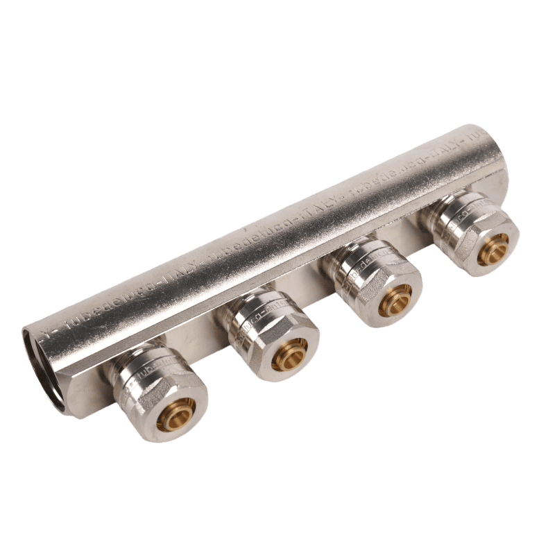
This nickel-plated brass manifold is a key part of HVAC and water supply systems. It uses a straight main pipe with multiple branch ports to split water flow. It is commonly used in underfloor heating, radiator systems, and similar setups. The manifold works with low-temperature hot water, such as underfloor heating water, and with normal domestic water. Each branch port sends water to a separate loop, which makes flow control simple and accurate. It is mainly used in home underfloor heating systems and water supply lines that need several outlets.
Model No: JX-10055
Material: CW617N Brass
Inlet Hole Thread (Female): 3/4″ and 1″, two options
Adapter size: Ø16×1.5/1/2×1.5
Center distance is 50mm
Shape: Throughflow with straight branches
Finishing: Nickel-plated
Standards: EN331
Thread Type: BSP
Application: Heating system
Maximum working pressure: 10 bar
Maximum Working Temperature: 120ºC
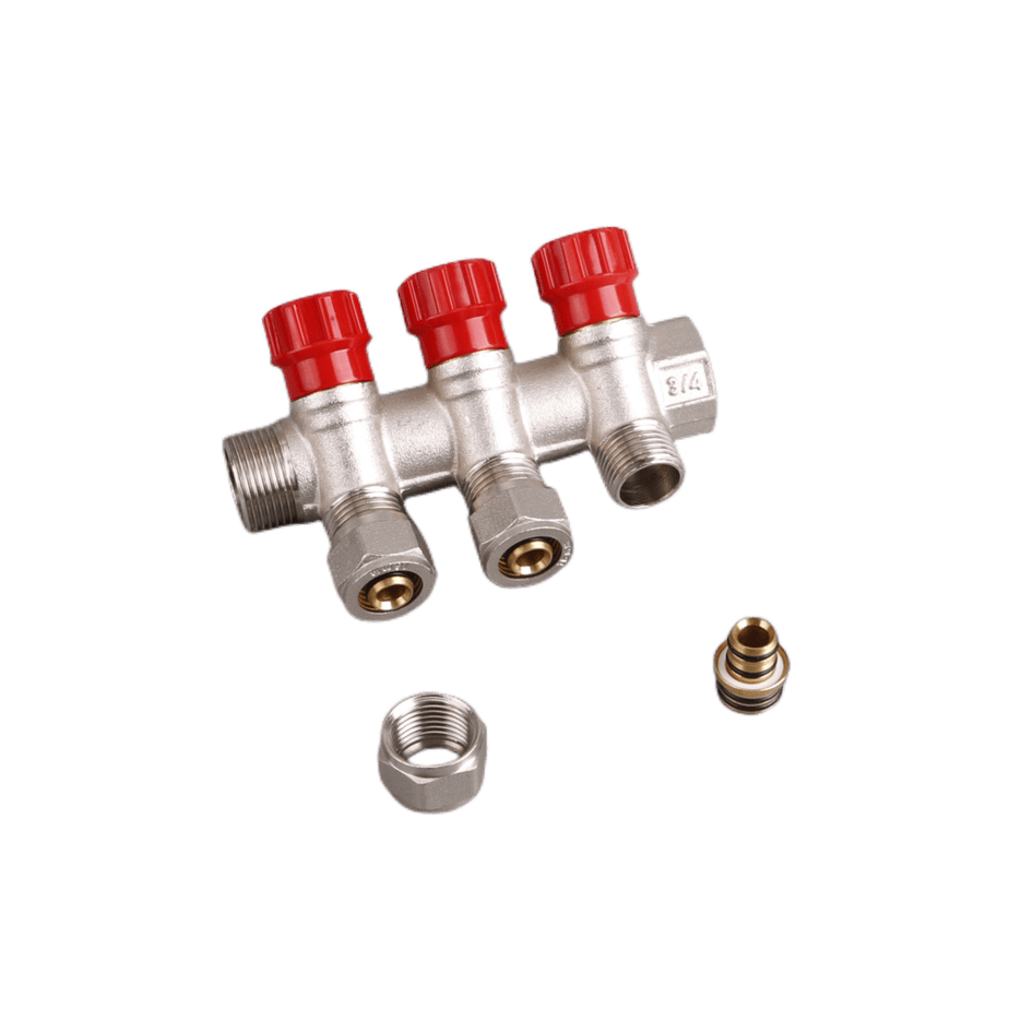
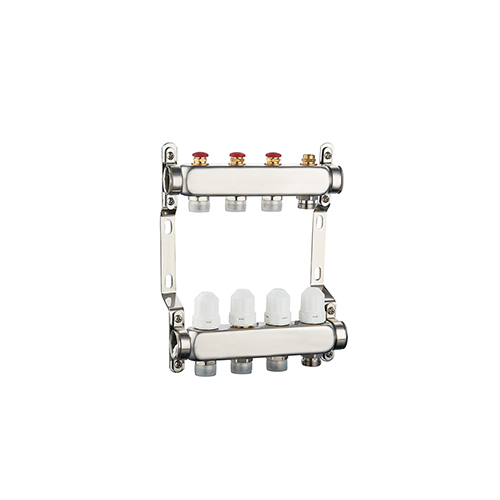
Central Heating Manifold
This central heating manifold is the main flow distribution part for underfloor heating and radiator systems. It has one main pipe and three branch ports, each fitted with an adjustment knob. It is designed for low-temperature hot water systems, typically operating at 60 ℃ or below. The red knobs allow you to adjust the flow for each circuit independently, enabling each zone to be controlled separately and with greater accuracy.
Model No.: JX-0708
Size: 3/4″, 1″
Material: CW617N, CW602N, CW510L
Head: Red hexagon head
Working temperature: -5-100˚C
Working pressure: 7bar
Standard: EN331, ISO228, DIN259
Seal material: PTFE
Connection: BSP
With NBR o-ring
Application: Radiant floor heating systems, Hydronic heating systems
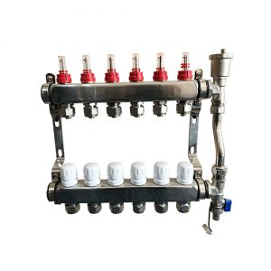
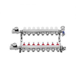
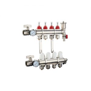
Underfloor Heating Manifold
This underfloor heating manifold is the main distribution part of an underfloor heating system. It utilizes an upper and a lower main pipe, featuring adjustable branch ports, and is well-suited for homes with multiple heating circuits. The red branch ports on the upper pipe send hot water to each heating loop. The white branch ports on the lower pipe collect the cooled water as it flows back. A matching bracket allows the manifold to be fixed on the wall, which makes installation and later maintenance easier. Each branch can be adjusted on its own. This allows for easy control of the temperature in each heating zone separately.
Model No.: JX-0702
Size: 1″
Adapter; 3/4″X20mm
Material: 304 Stainless Steel
Finishing: polishing
Connection thread; 3/4″&1/2″PEX loop
Mounting Location: Wall
Loop: 2-12 ways
With a Flowmeter/ without a flowmeter
4 Loop PEX Manifold
Max working pressure: 16 bar
Operating temperature: -10-110ºC
With NBR o-ring
Refrigeration Manifold Gauge
This refrigeration manifold gauge set includes a dual-pressure gauge body, color-coded high-pressure hoses, and a hanging hook. It is used for refrigerant charging, pressure checks, and vacuum work on refrigeration equipment like air conditioners and refrigerators. It is commonly used during air conditioner installation, system testing, and routine refrigerator maintenance.
Model No.: JX-0919
Size: 170 X120X50mm
Material: Brass
Read easily with large windows
Max working pressure: 600psi
Red Gauge (high): 0-500 psi
Blue Gauge (low): 0-250 psi
Color-coding on gauges, valves, and hoses
With a hook and 3 hoses
Used on all car A/C, commercial and domestic A/C, and refrigeration systems.
Equiced ACME Adapter
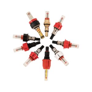
Manifold End with Drain Valve
This manifold accessory comes with a drain valve, a main connection port, and a sealing cap. It is used at the end of underfloor heating or heating manifolds and also supports system drainage. The valve features a lever handle, making it easy to open and close. It allows water replacement, dirt discharge, and pressure release during system use or maintenance. This part is mainly installed at the end of the underfloor heating manifolds.
Model No.: JX-0925
Size: 1″, customized
Material: CW617N, CW511L, Cw602N
DN25 1″ Automatic Air Vent End Unit
Automatically release the air
With a drain valve
Max Working pressure: 16 bar
Max Discharge pressure: 2.5 bar
Max working temperature: 150ºC
Forging brass with sand-blasted
Connection: BSP, ISO228
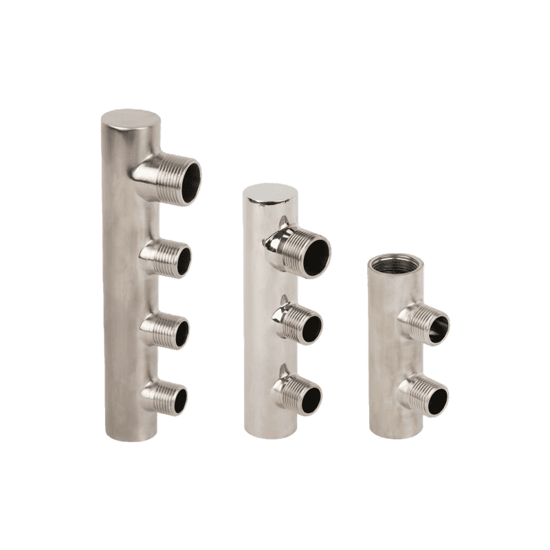
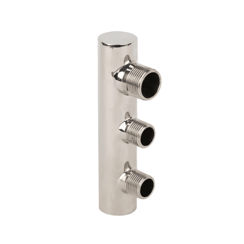
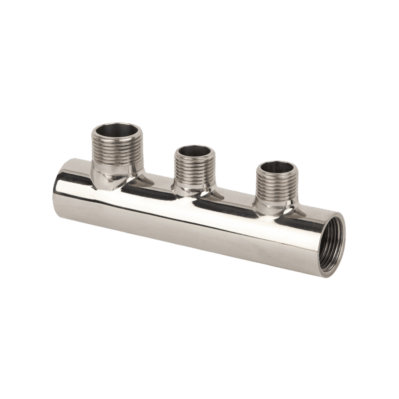
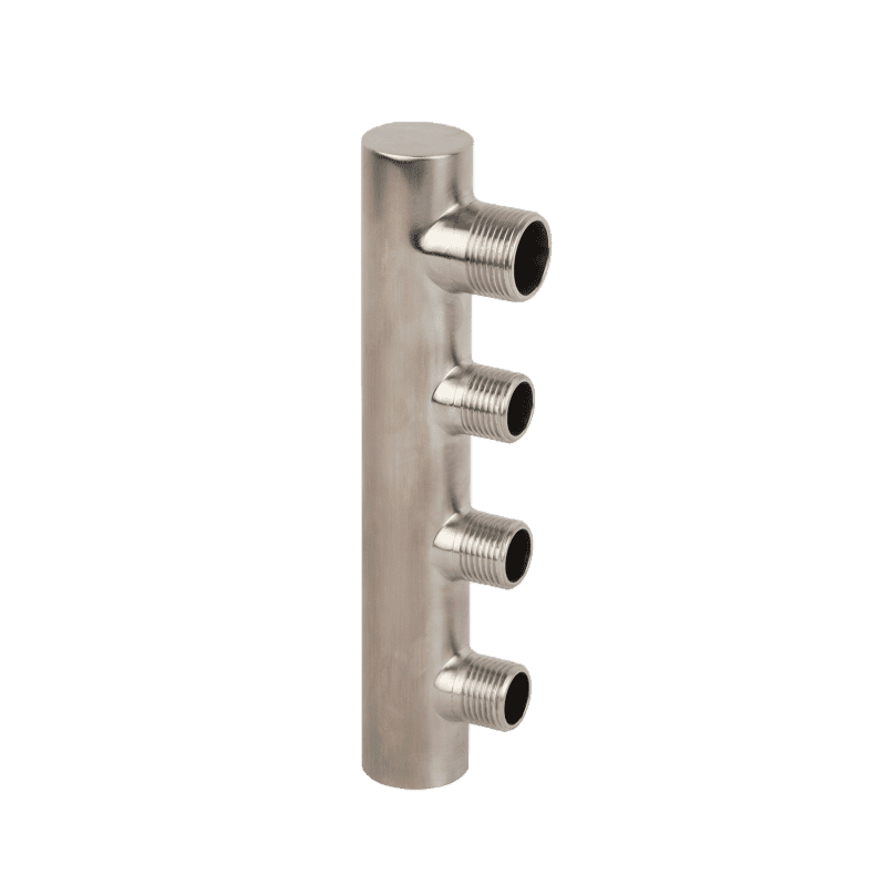
Stainless Steel Manifold Pipe
This stainless steel manifold pipe uses a long main pipe with several side outlets. It is designed for splitting a single main water or fluid line into multiple branches in water supply and HVAC systems. The top and bottom ends connect to the main pipeline. The side ports connect to branch pipes. This layout allows a single fluid source to flow evenly to different lines in a simple and efficient manner.
Model No.: JX-1006
Materials: Stainless steel AISI 304L and SS316
Finishing: Polishing
From 2 loops to 13 loops
Main connection thread: 1″F
Thread connection: BSP, NPT
Working pressure:150 PSI
Connection: Female thread ISO 228/1 of 1/2″
Max working temperature 110°C
Max working pressure 10 bar
Testing Pressure: 0.8 MPa, 100% testing
Thread: G, BSP, NPT
Branch distance: 50/55mm
FAQs of Tri Clamp Manifold
1. What is the accuracy advantage of the Tri Clamp manifold?
Precision index industry top, and 100% full inspection guarantee:
Testing equipment: Each processing equipment is supported by a Hexagon coordinate measuring instrument (Accuracy ±0.001mm). 100% of finished products pass a “size full inspection + sealing test + flow resistance test.”
Actual effect: When matched with Plumberstar sanitary valves, the connection gap is ≤0.03mm, the seal leakage rate is ≤1×10 Pa·m³/s, and the flow resistance coefficient is 15% lower than that of the same industry, ensuring stable medium flow (fluctuation ≤2%), especially suitable for high-precision fluid control systems.
From Get Er Brewed – Brewing Beer
2. What is the Tri Clamp manifold manufacturing process?
The ex-factory pass rate is ≥99.9%.
Details are as follows:
Raw material procurement: We exclusively use 304/316L coils from Taiyuan Iron and Steel and Baosteel (tolerance: ±0.01mm), as well as imported Hastelloy blanks (German VDM brand).
Raw material inspection: Use a spectrometer to test chemical components (testing time ≤30 seconds per piece). Use ultrasonic flaw detection (detection depth ≤20mm, defect detection rate 100%).
CNC machining: Use CNC lathes to process the tube body (speed 8000/rpm). Use machining centers to mill flanges (positioning accuracy ±0.005mm).
Salt spray test: Use neutral salt spray test chambers.
Full-size inspection: Use coordinate measuring machines to test key dimensions.
Appearance inspection: Use endoscopes to check the inner surface (no scratches, no impurities).
Finished product packaging: Package by standard classification. Each package comes with a quality traceability card (including batch number, raw material furnace number, and test data).
3. Can customized structures be provided for the tri-clamp manifold?
Standard Structures:
T-manifold (2 in 1 out / 1 in 2 out), Y-manifold (split angle 45°, flow resistance 30% lower than T-type), Multi-way manifold (3–10 channels, branch spacing ≥50mm), Shunt manifold (main pipe to multi-branch, shunt uniformity ±3%), Confluence manifold (multi-branch to main pipe, no turbulence during confluence)
Structure design: flow channel fillet transition (R≥ 3mm), no right-angle dead angle, weld adopts internal welding + polishing treatment (Weld clearance ≤0.2mm), avoid medium residue;
Material compliance: 100% of parts in contact with medium pass FDA 21 CFR Part 177 certification, heavy metal migration (Pb≤0.01mg/kg, Cd≤0.005mg/kg, As≤0.003mg/kg) far below the national standard limit;
detection guarantee: each batch of sampling for microbial detection (total colony count ≤10CFU/g), particle count detection (≥50μm particles ≤3/m²), can provide a complete GMP compliance report, and is the pharmaceutical and food industry’s preferred brand.
CNC workshops manufacturing
6. What is the difference between brass and stainless steel Tri Clamp manifolds?
Brass and stainless steel tri-clamp manifolds differ in corrosion resistance, temperature tolerance, cost, and applications.
Stainless steel—especially 304/316L—has better sanitary performance. It’s ideal for the food and pharmaceutical industries.
Brass is extremely durable and resistant to high pressure. It works well with other brass fittings. People often prefer it for heating and plumbing systems because of its sturdiness. But brass can have dezincification issues. For large systems, brass also incurs higher costs.
7. What materials are available for the tri-clamp manifold?
①304 stainless steel: Chemical composition Cr18%-20%, Ni8% -12%, C≤0.08%, Tensile strength 515-689MPa, Yield strength ≥205MPa, Adapt to temperature-20℃~120℃, Medium for water, juice, normal temperature chemicals scene, cost-effective, accounting for 60% of total sales
②316L stainless steel: Ultra Low Carbon(C≤0.03%), Mo2% -3%, tensile strength 485-655MPa, yield strength ≥170MPa, chloride ion resistance ≤2000ppm, suitable for pharmaceutical, seawater desalination, weak corrosion chemical scene, accounting for 35% of total sales.
8. What is the pressure test standard for the Tri Clamp manifold?
The pressure testing of the Plumberstar Tri Clamp manifold follows strict international standards and internal factory controls. All tests are conducted in a clear and repeatable manner to ensure safety and reliability for global markets.
Test medium:
Clean tap water is used.
All air inside the pipeline is fully discharged before testing to avoid false readings.
Test equipment:
An automatic hydraulic test machine is used, with an accuracy of ±0.001 MPa.
Pressure sensors and data recorders capture the full pressure curve in real time.
Test method:
Every finished product is tested. There is no sampling inspection.
Each unit generates its own pressure test report, which includes the batch number, test time, and pressure curve.
This data is fully traceable.
Handling of nonconforming products:
Any product that shows leakage or deformation during testing is scrapped immediately.
Repair is not allowed.
Scrap items are destroyed through a centralized process and fully documented.
9. Do you maintain QC documentation for traceability for manifolds?
Product identification labels
Each valve and heating manifold is marked with a unique, traceable identifier (such as a serial number, batch number, or traceability code).
Records of identifier generation and application are retained, and all identifiers are linked to the complete traceability document system.
Production and order tracking records
Production records clearly document the destination market, shipment details, and associated customer information for each order.
Raw material and component traceability reports
Traceability test records are maintained for all key materials and components, including brass bars, stainless steel, seals, fittings, and other critical parts.
2) Inspection and Testing Traceability Documents
Factory inspection reports
Inspection reports comply with the valve testing standards required by the destination market (such as EN standards for the EU or API standards for the USA).
These reports cover core performance indicators, including sealing performance, pressure resistance, and flow capacity.
Type test reports
Type testing is conducted for valve models exported for the first time or after any structural or design modification.
The reports meet the applicable standards of the destination country.
Destructive test reports (when required)
If requested by customers or required by local regulations, destructive testing is performed.
Reports clearly state the applicable standards, test methods, parameters, and final results.
3) Export Compliance and Regulatory Traceability Documents
Customs clearance documents
Commercial Invoice (CI), Packing List (PL), and Bill of Lading (BL) clearly record the quantity and batch correspondence of valves and heating manifolds shipped under each order.
Certificate of Origin (CO)
Used for tariff preference purposes in certain countries and as proof of origin when required by customers.
Mandatory certifications
Including but not limited to: CE marking for the European Union, CSA certification for Canada, cUPC certification for the United States, WaterMark certification for Australia
Material compliance reports
Some customers require additional test reports, such as REACH and RoHS, confirming that valve and manifold materials do not contain restricted hazardous substances.
4) Distribution and After-Sales Traceability Documents
Logistics and transportation records
Transportation routes, handling records, and—if required—temperature and humidity conditions during transit are documented to trace potential transport-related issues.
Customer receipt and acceptance records
Customers confirm receipt of the products, including identifier codes, quantities, and condition.
These records serve as formal proof of delivery.
After-sales service and recall records
If issues arise after export, all maintenance actions, recalled batches, corrective measures, and resolution results are fully documented.
5) Key Focus for an Export-Oriented Factory
As a manufacturer specializing in the export of valves and heating manifolds, the most critical documentation lies in: Core identity and material traceability (Section 1), Inspection and testing traceability (Section 2), Distribution and after-sales traceability (Section 4)
These documents form the foundation for regulatory compliance, customer trust, and long-term international market access.
10. How do you verify thread accuracy on each manifold?
To ensure the accuracy of threads for valves and heating manifolds (hydraulic separators/divers), we have 3 core aspects: design standards, production and machining, and inspection and verification. The thread requirements for these two products share certain similarities.
Clarify the Standards for Thread Specifications
For export to Europe, ISO metric threads (M series) or BSPT are typically used. Unified Thread Standards (NPT, UNEF, UN/UNC/UNF) are more commonly used. Valves and heating manifolds, with thread standards suitable for selected applications, such as NPT and G (ISO 228/Standard Pipe).
Threads for valves must comply with EN 10226 (specifications for pipe threads and fittings). Threads for heating manifolds, used in HVAC systems, are specified in standards such as EN 331 in Europe and ASME in the USA.
Common Thread Inspection Tools
Thread plug and ring gauges: These are fundamental inspection tools. The “Go” gauge should pass through the thread smoothly, while the “No-Go” gauge should not, allowing for quick verification of basic thread accuracy in terms of pitch diameter, pitch, and thread form. This is a rapid inspection method for mass production.
Thread gauges (plug/ring gauges): Used to check the dimensional accuracy of threads.
Thread Inspection for Valves
As valve threads are used for pipe connections, it’s better to thread a water pipe directly and turn it on /off for one more test after leakage approval.
Heating manifolds have multiple threaded ports, so the positional accuracy of each thread must be inspected to ensure the relative positions of all loop threads meet design requirements and avoid misalignment during pipe connection.
The first piece should undergo a full inspection to confirm machining accuracy during mass production.
Sampling inspections should be conducted according to AQL during the mass production process.