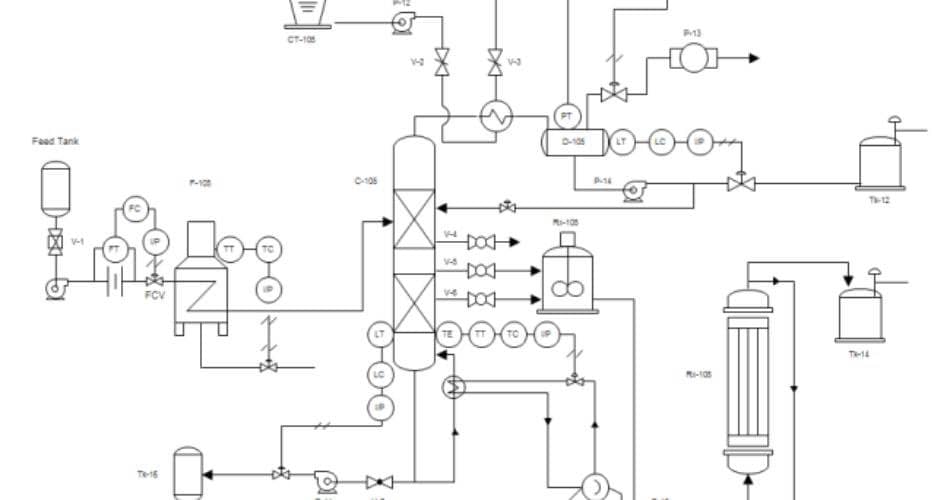
Piping and Instrumentation Diagram (P&ID): The Basics
Before getting into the intricate details of the valve symbols, let’s first look into the beauty where they are found: Piping and Instrumentation Diagrams (P&ID). A comprehensive, detailed map of a process system is a P&ID. It encompasses vessels, piping, control vessels, instruments, equipment, and process components.
To make things easier, let’s take an example. For instance, take P&ID. Google Maps gives engineers an overall view of the system’s organization and how its parts interconnect.
Moreover, suppose one wants to comprehend the little complex details of this system and its connection. In that case, one must decipher the valve symbols and other pieces on a P&ID. Understanding the system will boost your ability to design, execute, and fix it.

The Use of Piping and Instrumentation Diagram (P&ID)
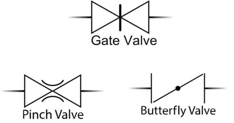
The effective use of P&ID involves comprehensive knowledge of these symbols and notations. These symbols are usually found in standard shapes with components like triangles, circles, lines, or a blend. They present various pieces on P&ID, such as sensors, pumps, and significant valves. Our focus here is on the valve symbols. The tow line (piping) attached to a boxy or triangular symbol represents a type of valve. For recognition, there are indicators. For instance, a gate valve symbol is depicted with a vertical line and a glove valve symbol with a small dark circle.
Follow these steps for the effective use of a P&ID:
- Follow the Legend: With a P&ID, there’s a legend that contains everything regarding the meaning of the symbols. This is your go-to guide to learn everything related to the diagram.
- Recognize the Flow Path: The next step is to follow the material flow through the system and figure out its movement from one part to the next.
- Notice the Details: Another important thing is that you should’ve thorough knowledge of the types of valves, their positions, and the sizes and types of instruments and pipes.
- Get Help from Colleagues: If you think you’re doing something wrong, get your fellow’s advice.
Functions That Valves Perform
Just like a faucet that controls water flow, valves are designed to regulate the start and stop of the fluids in the system. They are vital for the efficient and safe operation of the entire system.
The functions that valves perform include:
- Seclusion: Its primary role is to stop or start fluid movement as desired.
- Regulation: It controls the pressure or flow rate in the system.
- Prevention: Valves help you to avoid overpressure by exerting extra pressure on the relief system.
- Directional Control: With the help of valves, you can alter the direction of fluid flow.
- Something Special: You can prevent overflows by incorporating check valves and can remove undesired fluids through drain valves.
P&IDs vs. PFDs: Understanding the Difference
Many of us confuse P&IDs with Process Flow Diagrams (PFDs). Although at first glance, it seems they’re quite similar, they’re designed to perform distinct purposes. The primary purpose of a Process Flow Diagram (PFD) is to give an overview of the process flow and play a crucial role in comprehending the process and its significant parts. For instance, when you look at a city map that contains the main roads and landmarks. On the contrary, A P&ID gives a detailed representation of the entire system. It breaks down the process components like instruments, valves, pipelines, and connectivity with a valve diagram to make everything clear regarding the functioning and design of the system. For instance, when you want to get a detailed look at every small alley and building with the help of a detailed street map.
Understanding Different Valve Symbols
Let’s move on to the chief part: valve symbols. When you step into the Piping and Instrumentation Diagrams (P&ID) world, you realize that it’s filled with valve symbols and diagrams. The primary ones are the 2-way, 3-way, and 4-way valves. A thorough knowledge and understanding of such symbols is very important to work efficiently with P&IDs.
2-Way Valves
2-Way valves are the primary class of valve symbols presented in P&IDs. They are made of two equilateral triangles facing each other. For instance, ball valve symbols, gate valve symbols, plug valve symbols, etc. The key function of these valves is the regulation of the fluid flow so that the backflow doesn’t occur. They serve the purpose of controlling flow direction and carrying out on/off functions. In the diagram, 2-way valves are indicated by discrete lines, and the arrowhead represents the flow direction.
3-Way and 4-Way Valves
When we dive deep into the P&ID, we come across another category: 3-way and 4-way valves. Visually, the symbols of these valves are similar to the 2-way valve but have an additional triangle. This additional triangle means an extra way for the fluid flow. Additionally, the 3-way and 4-way valves are symbolized by an L-port or T-port nomination that explains the linkage points of the valve. These valves are known for their compatible nature with complex systems as they allow the fluid flow in various directions.
Let’s learn about some of the common types and symbols:
Gate Valves
A straightforward gate-like figure characterizes Gate Valves. The primary function of these valves is to regulate fluid flow. In terms of shape, this valve has a rectangular block intersected with a line. This valve works by lifting a gate out of the path of the fluid. They work perfectly when there’s a minimum blockage and proper fluid flow. However, gate valves cannot work properly for throttling purposes because they disturb the precise flow control.
Globe Valves
Next is the globe valve symbol. It has a more complicated internal structure than the gate valve symbol, which has a circle cleaved by a horizontal line. So, it serves to regulate the flow properly. With this globe valve design, you can adjust the flow through the valve, a perfect setting for situations where you want to control the flow. This complex internal organization of the valve symbol allows the moderate flow of the fluid.
Ball Valves
Ball valves are another important part of Piping and Instrumentation Diagrams (P&ID). Their design is indicated by a circle with a concrete line cutting through the middle, with a ball within the valve used to regulate the flow. Their durability and superb sealing capacity are the reasons for their popularity, making them a perfect option for controlling on-off applications. The simple design of the valve and symbol effectively ensures a rigid seal and simple working.
Butterfly Valves
As the name suggests, the symbol of a butterfly valve is like a butterfly, with two semicircles depicting the wings. This design permits the valve to regulate the flow in large pipe diameters, making it a popular choice for various applications. It promotes easy and swift flow regulation, suitable even for board systems where weight and space do matter.
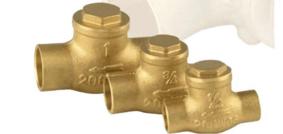
Check Valves
Another important part of the valve symbols is a check valve. Check valves contain a symbol that mirrors a single arrow or sometimes looks like a ball within the shell. This beauty serves the purpose of averting backflow in a system. The symbol mentions the direction of the fluid’s movement and ensures the fluid’s one-directional flow. Consequently, it prevents the reverse flow of the fluid from damaging the equipment.
Safety and Relief Valves
Lastly, there are safety and relief valves, which have a symbol like a spring-loaded figure to ensure the safety of the whole system. The valve protects the system from potential damage or failure by exerting extra pressure. As it embodies a spring in its structure, it turns the valve into an automatic valve. Its automatic nature opens it up automatically as the pressure excels at a predetermined level.
Final Thoughts
Valve symbols are essential to understand when it comes to the system’s operation, as they give you an inclusive audit of the system. Valve symbols on P&IDs are considered the universal language of fluid flow control. Therefore, mastering the symbols and their depiction on P&ID empowers you to navigate this complex system efficiently.