What is a Gate Valve?
A gate valve is a control valve that permits unrestricted media passage or stops the fluid flow. The primary advantage of a gate valve is its obstruction-free passageway. This may result in minimal pressure loss over the valve. Unlike butterfly valves, the open bore of a gate valve allows for the passage of flow during the pipe-cleaning process. However, because gate valves are slower than quarter-turn valves, they should only be used in the fully open or closed position. There are automated gate valves with either an electric or pneumatic actuator. Still, manual gate valves are more cost-effective due to their less use. Commonly, they are also known as sluice gate valves.
What is Globe Valve
Globe valves are valves that regulate fluid flow in conduits via linear motion. Their spherical bodies hold a movable disk or plug mechanism. This mechanism regulates fluid flow by closing, opening, or partially stopping the flow path of the valve.
Gate Valve Vs. Globe Valve: In-depth Guide
1) Gate Valve Vs. Globe Valve: Design
- Gate Valve Design
A gate valve is uncomplicated and can be used in various low-pressure-drop applications. This feature makes it one of the most widely used valves today. Gate valves are designed as full-port valves. This indicates that the valve outlet is the same size as the connecting pipe’s inner diameter. Full-bore gate valves have no impact on fluid flow. However, it does not cause pipeline pressure to decrease.
- Globe Valve Design
Globe valves are available in a variety of shapes or design variations. All three kinds stop or restrict the flow of fluids in the same way. However, each form alters the flow path and, consequently, the head loss.
- T- or Z globe valve
T-shaped or z-shaped globe valves are the most common. Despite the “t-pattern” for the valve’s profile, “z-shaped” may be a more accurate description of how fluid flows through the device. In a standard Z-shaped globe valve, the flow of water reverses in a pattern resembling the letter Z. These Z-shaped standard valves have the most significant head loss.
- Angle globe valve
Due to the 90-degree angle between its inlet and outlet ports, an angle valve can function as a valve and pipe elbow. This globe valve minimizes head loss because there is only a single change in fluid direction.
- Y-globe valve
The Y-pattern globe valve is an alternative to the T-pattern globe valve. Although fluid flow is in a direct line or “z-pattern,” the bonnet and stem are angled relative to the valve body to create a “y-pattern” valve profile. Repositioning the valve seat makes the flow path more direct, reducing head loss.
Gate Valve Vs. Globe Valve: Components
- Gate Valve Components
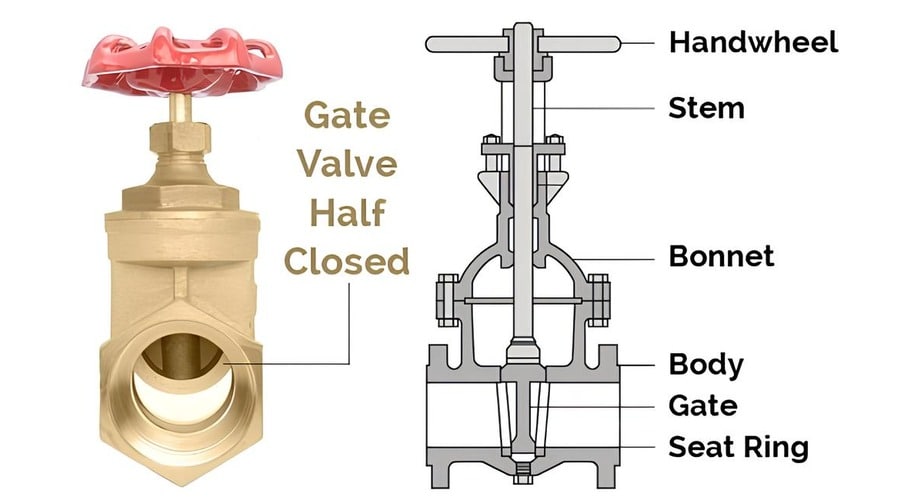
The seven major components of a gate valve are the handwheel, stem, gasket, bonnet, valve body, flange, and gate. A flanged or threaded gate valve attaches the valve to an application. In addition, depending on the design and application, the handwheel, stem, bonnet, and gate can have various designs to facilitate multiple applications. However, the primary function of gate valve components remains unchanged. Continue perusing to locate the relevant sections.
- Globe Valve Components
Globe valves are comprised of the following components:
- Body: The valve’s body is comprised of cast iron, carbon steel, stainless steel, or alloys.
- Bonnet: The uppermost portion of a valve that contains the stem and packing.
- Stem: A threaded rod attached to the disk or plug that directs the movement of the valve.
- Disk or Plug: The movable component that controls flow by obstructing the flow path.
- Seat: The immobile component against which the disk or plug seals to prevent fluid passage.
- Handwheel or Actuator: The mechanism used to manually or automatically operate the valve.
Gate Valve Working
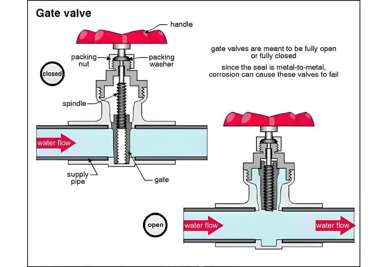
A gate valve functions similarly to other types of valves. To access the valve, turn the handwheel, which raises or lowers the gate via threads on the stem. Opening or closing a gate valve ultimately requires more than 360° rotations. When the gate is raised, it reveals the inlet to the outlet, allowing the media to flow through unobstructed. When the gate is lowered, it closes and prevents media from passing through.
For a gate valve, the relationship between the vertical travel of the gate and the flow rate is nonlinear, with the most significant alterations occurring near complete closure. When used to regulate flow, the moderately high velocity of the flow at partial opening causes gate and seat wear, which, along with potential vibrations of the gate, shortens the valve’s service life. A gate valve should only be used for on/off control.
Globe Valve Working
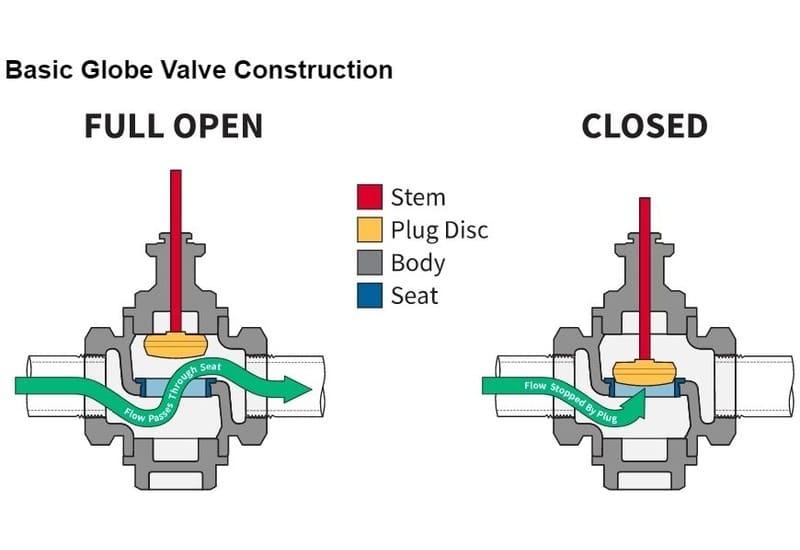
The handwheel of a globe valve must be turned more than 360 degrees to open or close the valve completely. The valve body, bonnet, handwheel, stem, and plug are the primary components of a globe valve. Media enters the inner of the valve through an inlet and exits through an outlet. The bonnet shields the valve’s threaded components and attaches to the valve body. The threaded stem raises or lowers the plug as the user rotates the handwheel. Raising the plug allows media to circulate by expanding the orifice. Lowering the plug onto the valve seat prevents flow by sealing the orifice.
In contrast, raising the disc increases the flow rate. The flow rate maximizes when the disc is raised to its utmost position. The fluid flow rate is controlled by the proportional movement of the disc through the stem.
Gate Valve Vs. Globe Valve: Flow Properties
The gate valve is bidirectional straight-through, meaning its design permits flow in both directions. The discharge only changes when the gate valve is closed and the flow is stopped.
A globe valve, on the other hand, has a flow path with more turns. Flow can follow a z-shaped path (T- or Z-valve), a path (Y-valve), or a path with a 90° turn (angle valve).
A globe valve has an inlet and an outlet port because it controls flow in a specific way. Typically, the flow direction of a valve is indicated by an arrow on the body’s exterior. In addition, the flow change causes a significant decrease in pressure through the globe valve. In contrast, the pressure decrease of a gate valve is minimal.
Gate Valve Vs. Globe Valve: Valve Functions
Globe valves can restrict flow, whereas gate valves cannot. Within the globe valve, the flow diverges and becomes parallel to the valve seat. The design of globe valves makes them efficient flow regulators. At larger diameters, globe valves are no longer appropriate for flow control. Gate and globe valves can be manually, pneumatically, or electrically operated.
Gate Valve Vs. Globe Valve: Sealing Surface
When a gate valve opens and closes, the sealing surface on the gate and the sealing surface on the seat are always touching and friction against each other. This makes the sealing surface easily worn. This is particularly problematic when the valve is closed, the differential pressure is high for the gate, and the sealing surface wear is worse. When the globe valve opens, the plug’s seat and sealing surface are no longer touching. This means that the sealing surface wears less quickly.
However, damaging the globe valve’s sealing surface is easy if the medium has solid particles. The sealing surface on a gate valve can seal itself when the pressure of the media presses tightly against the sealing surface on the valve seat. This makes a tight seal that doesn’t leak.
Gate Valve Vs. Globe Valve: Drops in Pressure
When gate valves are fully opened, there isn’t much pressure drop or fluid trapping because of its design. Also, when these valves are closed, they stop all fluid flow. This is how globe valves are different. A globe valve should cause a significant drop in pressure at full open. Although globe valves have S-shaped passageways, they make it more difficult for fluid to flow than gate valves do.
Gate Valve Material
Gate valves are utilized in numerous applications and come into contact with various media. It is essential to consider the construction material used for valves to prevent premature valve failure and system delays during valve operation. Consider the following factors when selecting materials for a gate valve:
- Media composition (whether explicit or filled with particles)
- Material compatibility with the media used
- How long the valve gets exposed to the media
- Operating pressure
- Service temperatures
- Effectiveness of coating on materials
- Material availability and cost
Gate valve body materials
- Brass gate valve
In conditions where PVC gate valves would break, brass valves are a viable alternative.
- Brass gate valve features
Brass gate valves operate with media temperatures ranging from -20 °C to 120°C and pressures ranging from 0 to 16 bar. Brass gate valves are more expensive than PVC gate valves but less expensive than stainless steel gate valves.
- Application of brass gate valve
Brass can withstand higher temperatures than PVC, making it ideal for residential piping. Brass is highly corrosion-resistant, making brass gate valves suitable for manufacturing industries that utilize natural gas or potable water.
Stainless steel gate valve
Stainless steel is the most durable, heat-resistant, and corrosion-resistant material compared to brass and PVC. Compared to brass and PVC, stainless steel can withstand a more comprehensive range of temperatures (from low to high) and pressures.
- Used in the manufacturing of gate valve bodies and internal components
- Stainless steel gate valves have a simple body design that facilitates repair, cleansing, and maintenance
- They are used in liquid, gas, and steam applications
- They are more expensive than PVC, brass, and bronze gate valves
- They require a larger installation area than brass or PVC gate valves
- Uses for stainless steel gate valves
Stainless steel is utilized in marine and industrial uses due to its long-lasting and resistance to corrosion. Industrial applications, such as transporting natural gas and crude oil and slurry applications, are examples of prevalent applications.
- Domestic drinking water applications because the material does not percolate into the water.
Bronze gate valve
- Bronze gate valve features
- Outstanding machinability, tensile strength, and corrosion resistance
- Used in the production of relatively small gate valves for low-pressure applications
- Bronze gate valves are typically used for water pipes and equipment conduits with pressures of 300 psi (20 bar) or less and temperatures between -20 ° C and 150° C.
- It is more expensive than PVC but cheaper than brass and stainless steel
- Bronze has more excellent corrosion resistance than cast iron but less than PVC or brass.
- Although more expensive than PVC, bronze is cheaper than brass or stainless steel.
- Bronze gate valve applications
Due to its higher lead content, bronze is not commonly used for drinking water applications. Bronze is widely used for fluid control in low-pressure manufacturing industries because it is compatible with steam, air, and gas. Additionally, the material is utilized in HVAC and marine applications.
Globe Valve Material
Cast iron or brass/bronze is typically used for globe valve bodies in low-pressure applications. In contrast, forged carbon steel or stainless steel is used for higher pressures and temperatures. Material specifications for the body typically include all components under pressure, whereas “trim” refers to features other than the body, such as the seats, the disc, and the stem. Larger sizes are designated by an ASME class pressure rating and ordered with bolted or welded standard flanges. Because pressure loss through the valve may be a concern, sizing a globe valve is more complex than sizing other valves.
Gate valve applications
There are numerous industrial and residential applications for gate valves.
- Slurries: Gate valves are frequently used in applications where slurries serve as the medium. Because a gate valve has an unobstructed fluid passageway, the slurry can readily pass through the valve. Additionally, knife gate valves can effortlessly cut through sediment to close.
- Water gate valves: Since flow control is typically not required for water applications, water gate valves are commonly utilized. The valve can be completely open or closed, enabling water regulation.
Applications of Globe Valve

When flow control is required in industrial processes and systems, globe valves are highly recommended. Globally, valves assure safety and air tightness in high-point vents and low-point drainage. Compared to other valves, globe valves have a robust closing mechanism less prone to leaks and defects.
These valves are the optimal option for addressing leakage issues in residential and commercial settings. Typical industrial applications for globe valves include cooling systems, chemical feed systems, feed water systems, turbine lube systems, and any other system where pressure reduction is not a concern.
Globe valves are utilized in numerous applications where constant fluid flow is not required, such as chemical feed systems and turbine lubricant oil structures. In addition, globe valves are primarily utilized in process plants, power plants, and effluent treatment facilities.
Globe valves are required to control the fluid flow in lubrication systems, steam lines, and coolant pipelines. Globally, valves for commercial and residential buildings requiring upstream fluid flow endure high demand.
Gate Valve Vs. Globe Valve: Working Temperature and Pressure
Both gate and globe valves are made from brass, stainless steel, and bronze. Each material has different working temperature conditions. However, a standard bronze gate valve has a working temperature range of -10˚C-120˚C with a working pressure of 16 bar (232 psi). The globe valve is made of brass alloy, such as leaded brass C3604. It has a working temperature ranging from -30 °C to 120°C, with an operating pressure of 16 bar.
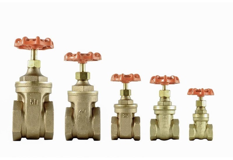
Gate valve size:
| Size | Pressure |
| 1/2″ (DN 15) | 16bar/232psi |
| 3/4″ (DN 20) | 16bar/232psi |
| 1″ (DN 25) | 16bar/232psi |
| 1 “1/4 (DN 32) | 16bar/232psi |
| 1 “1/2 (DN 40) | 16bar/232psi |
| 2″ (DN 50) | 16bar/232psi |
| 2 “1/2 (DN 65) | 16bar/232psi |
| 3″ (DN 80) | 16bar/232psi |
Globe valve size:
| DN | Sizes (Inch) | L | H |
| 5 | ½” | 62 | 101 |
| 20 | ¾” | 74 | 115 |
| 25 | 1″ | 90 | 125 |
| 32 | 1¼” | 100 | 150 |
| 40 | 1½” | 115 | 159 |
Choosing Between Gate Valve and Globe Valve
Both globe valves and gate valves are great shut-off valves. But if you have to choose between them, neither valve will work better in every situation. Consider the following points into consideration:
Regulating flow: If you need to change the flow in an application, choose a globe valve.
Flow Capacity: Choose a gate valve if you need a significant amount of flow.
Flow direction: Choose a gate valve if you need flow to move in both directions.
Sealing: Choose a globe valve if you require a valve that seals well.
Pressure drop: Choose a gate valve if you need a minimal pressure drop.
Contaminated media: Select the gate valve if an application has slurry or other contaminated media.
Globe Valve Vs. Gate Valve: Which One Is Better
When compared to gate valves, globe valves offer better long-lasting and sealing. However, the pressure drop of a gate valve is much lower. Gate valves are great for applications needing bidirectional flow, whereas globe valves are preferable for applications requiring more precise flow control.
What Issue did We Resolve in this article?
After reading this post, gate valve vs. globe valve, we explain the complete difference between globe valves. We concluded that Globe valves are typically employed for flow regulation, whereas gate valves are more suitable for ON/OFF applications. Globe valves are more complicated and costly than gate valves, but their efficiency is superior. When selecting between the two, it is crucial to consider the application’s specific requirements.