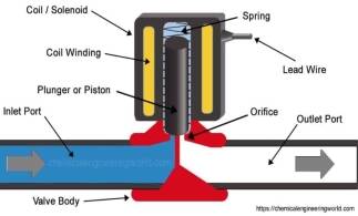
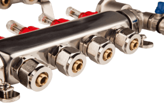
Passing a pressure test before shipment does not mean valve quality control is complete. Some quality issues originate during material selection, machining, or assembly, such as incorrect body material, thread dimensional drift, poor sealing-surface machining, or improper assembly preload. Relying only on final inspection makes process deviations difficult to detect in time and cannot ensure consistency between production batches.
Based on the actual production flow, this article explains quality control from pre-production technical review, raw-material and critical-component inspection, valve body machining, and assembly through pressure and functional testing, final inspection, packing, and shipment. It also covers inspection priorities and common defects for different valve types, showing how to control quality issues at the process where they occur.
1. What Is Valve Quality Control?
First, we need to understand the basic definition and scope of valve quality control:
1) Definition of Valve Quality Control
Valve Quality Control is the process of using inspection, measurement, testing, and process control to verify that a valve, from raw material through finished product, meets drawings, purchase specifications, product standards, and customer requirements. It covers dimensions, materials, and connections, and also verifies required sealing, opening/closing, pressure-regulating, temperature-control, or safety-protection functions. For mass production, quality control must also ensure consistency.
2) Which Production Stages Does Valve Quality Control Cover?
Valve quality control usually starts with pre-production technical review, followed by inspection of raw materials and purchased parts, valve body forming, machining, assembly, finished-product testing, final inspection, packing, and shipment. Each stage addresses different risks. Incoming inspection mainly prevents wrong materials or parts; machining controls threads, dimensions, and sealing interfaces; finished-product inspection verifies pressure integrity, sealing, and actual function.
2. Pre-Production Technical Requirements and Quality Plan Review
Pre-production technical review determines whether machining, assembly, and inspection can follow one consistent standard. Before mass production starts, the product requirements, quality control points, and inspection conditions must be clearly confirmed.
1) Verify Valve Specifications, Drawings, and Applicable Standards
Before production starts, cross-check the drawings, order specifications, and service-condition requirements. Confirm valve size, pressure rating, media compatibility, temperature range, connection type, and construction. Distinguish PN from Class pressure-rating systems, and ensure DN/NPS, thread, and flange standards match the project requirements. Pressure testing may follow EN 12266-1, ISO 5208, API 598, or the applicable product standard, depending on valve type and project specification. Plumbing, pressure-regulating, temperature-control, and potable-water valves also require verification of the relevant product standards, Kv/Cv, temperature-control performance, and material compliance.
2) Define Critical Quality Control Points and Acceptance Criteria
Set quality control points according to valve type. For on/off valves, focus on sealing-surface accuracy, body integrity, and smooth operation. For regulating valves, control trim travel, pressure-regulation accuracy, and spring rate. For temperature-control valves, focus on sensing-element response and mixing-ratio accuracy. For safety valves, control set pressure and check-sealing performance. Every control point should have measurable acceptance criteria; vague judgments such as “visually acceptable” or “feels normal” should not be used.
3) Set Witness Points, Hold Points, and Third-Party Inspection Requirements
Establish graded quality-control checkpoints in the inspection plan. For projects requiring third-party witnessing, define the Hold Points, Witness Points, and document-review requirements in advance. Depending on the contract, material documentation may include EN 10204 3.1 or 3.2 inspection documents. Where third-party witnessing is required, also define the inspection body, witness scope, and acceptance stages.
4) Confirm Test Equipment, Personnel Qualifications, and Calibration Status
Before mass production, verify the calibration validity of key equipment such as calipers, pressure test benches, air-leak testers, and torque testers. Do not use equipment with expired calibration. Testing, QC, and assembly personnel must hold the required qualifications, and new operators should pass practical pre-job assessments.
3. Quality Control Priorities for Different Valve Types
Many valves use brass bodies, but their functions vary significantly, so their QC priorities are different.
| Valve Category | Typical Products | Main Quality Control Priorities |
| General On/Off Valves | Ball Valve, Gate Valve, Globe Valve | Sealing, operation, torque, connection dimensions |
| Flow and Pressure Regulating Valves | PRV, Balance Valve, Needle Valve | Regulation accuracy, flow, pressure stability |
| HVAC and Temperature-Control Valves | TRV, Mixing Valve, Electric Valve | Temperature control, trim response, actuator |
| Safety and Protection Valves | Check Valve, Safety Valve, Backflow Preventer | Opening, closing, pressure relief, backflow prevention |
1) General On/Off Valves
Ball valves, gate valves, and globe valves mainly open or shut off flow. The first requirements are therefore smooth operation, reliable shutoff, no external leakage, and correct connections. For a brass ball valve, for example, ball roundness and surface quality, the PTFE seats, stem sealing, and assembly preload all affect operating torque and sealing performance.
2) Flow and Pressure Regulating Valves
Pressure-reducing valves and balancing valves cannot be qualified by body pressure testing alone. For example, a PRV may have no external leakage, but if the outlet is set to 3 bar and drifts to 4 bar during operation, it still fails functionally. These valves therefore require pressure-regulation, stability, or flow-performance testing.
3) HVAC and Temperature-Control Valves
TRVs, thermostatic mixing valves, and motorized two-way and three-way valves add temperature or automatic control functions. In addition to body and sealing checks, inspect sensing-element response, valve trim travel, temperature-control accuracy, actuator operation, and the power-off condition.
4) Safety and Protection Valves
Check valves, safety valves, and backflow preventers have different control priorities. A check valve must allow normal forward flow, close reliably against reverse flow, and operate without disc sticking. A safety valve must meet the specified set pressure, opening, and reseating performance. Therefore, applying one hydrostatic test to every valve does not constitute complete quality control.
4. How Should Raw Materials and Critical Components Be Inspected?
The sampling ratios and dimensional or hardness control values below can serve as internal factory references. Actual acceptance requirements should follow the material grade, product drawing, applicable standard, and customer quality plan.
1) Valve Body Material, Material Certificates, and Composition Verification
For brass, cast iron, and stainless-steel valve body materials, verify material certificates, batch numbers, and chemical composition. For volume orders, conduct spectrometer sampling according to the inspection plan; for example, an internal quality plan may set a sampling rate of about 3%. Brass hardness can also be used as a supplementary control item. Some brass bodies, for example, may be internally controlled within 80–120 HB, but the actual range should follow the material grade and product design requirements.

Brass Material Spectrometer Test
2) On/Off Valves: Ball, Stem, Seat, and Seals
The ball surface must be smooth, free of scratches and high or low spots, and ground to the required accuracy to prevent seat damage and internal leakage. The stem must be straight and burr-free. For high-precision stems, concentricity can be controlled as a critical dimension; an internal drawing may specify ≤0.02 mm, for example, to ensure smooth operation. Seat faces must be flat. Rubber seals must show no deformation, aging, or contamination, should have uniform elasticity, and must not leave gaps at the sealing interface.
3) Regulating Valves: Trim, Diaphragm, Spring, and Adjustment Components
Valve trim flow passages must be smooth, dimensionally accurate, and free of machining burrs. Diaphragms should remain flexible, crack-free, heat-resistant, and aging-resistant. For products sensitive to pressure-regulation performance, set quantitative requirements for spring consistency within the same batch; for example, control spring-force variation to about ±5% to prevent pressure drift caused by uneven spring force. Sample-check adjustment assemblies for compatibility to ensure accurate linkage and stable, linear adjustment.
4) Temperature-Control Valves: Sensing Element, Trim, and Actuation Components
The sensing element must meet sensitivity requirements without delayed temperature response. Trim linkage clearances should be uniform and free from sticking. Electric actuators must open and close smoothly when energized and achieve the specified travel. Sample each batch for temperature-control error to confirm that control accuracy meets HVAC operating requirements.
5) Safety and Protection Valves: Springs, Discs, and Check Components
Check-valve springs should return quickly with stable force. Disc sealing surfaces must be defect-free and seat tightly when closed. Safety-valve assemblies must respond accurately to pressure without sticking or delay. Sample each batch under simulated overpressure and backflow conditions to verify effective safety protection.
6) Batch Identification and Material Traceability
Manage raw materials and components by batch number, linking each batch to the manufacturer, receipt date, and inspection records in a traceability log. When a quality issue occurs, the material batch, supplier, and inspection records can then be traced directly, allowing the root cause to be identified quickly and preventing repeat batch defects.
5. Quality Control During Valve Body Forming and Machining
Valve body forming and machining are critical to structural accuracy, pressure integrity, and connection reliability. Weak process control can lead to pinhole leakage, dimensional deviation, thread failure, and poor fit.
1) Visual Defect Inspection of Cast, Forged, and Hot-Forged Valve Bodies
Perform 100% visual inspection of formed blanks, focusing on surface porosity, pinholes, cracks, inclusions, looseness, incomplete filling, and similar defects. Use preliminary water-immersion screening for small hidden pinholes so defective blanks can be removed before unnecessary machining. Strictly control forming parameters: for castings, focus on pouring temperature, mold filling, and venting; for hot forgings, check forging temperature, die condition, folds, underfill, and deformation.
2) Valve Body Wall Thickness, Critical Dimensions, and Machining Allowance
Use calipers and micrometers to sample-check key parameters such as body wall thickness, flow-passage dimensions, and flange thickness. Wall thickness should be uniform with no thin areas, and machining allowance should be sufficient and reasonable. This prevents pressure leakage caused by thin walls and scrap caused by insufficient allowance. Control critical dimensions to the drawing tolerances. For some machined mating dimensions, internal control can reach ±0.05 mm.
Valve Dimensional Measurement
3) Inspection of Threads and Other Connection-End Dimensions
Use standard thread ring gauges and plug gauges for GO/NO-GO inspection of pipe threads and connection ports. Reject incomplete thread forms, burrs, inconsistent thread depth, stripped threads, and similar defects. Pay particular attention to defects at the thread root, a common hidden source of installation leakage. After machining, remove burrs and verify dimensional accuracy.
Mass machining must also control dimensional drift caused by tool wear. For example, threads may be correct on ball valves produced early in a batch, but as the tool wears, later parts may accept only 1–2 threads of engagement. Such parts can still look acceptable and may even pass pressure testing. Control this risk through first-article inspection, in-process patrol inspection, and tool-life management.
Thread GO/NO-GO Inspection
4) Machining Quality of Valve Trim, Ball, and Sealing Mating Surfaces
Sealing mating surfaces and ground ball surfaces must be smooth and flat, without scratches, high or low spots, or tool marks, and must meet the required microscopic flatness so they fully contact when closed. Trim flow passages must be free of burrs and residual debris that could later break loose, jam the sealing surfaces, and cause operating failure or leakage.
5) Segregation, Rework, and Reinspection of Nonconforming Parts
Place all nonconforming machined parts in a dedicated, identified quarantine area and prevent them from mixing with accepted parts. Define standardized rework procedures for repairable parts and repeat the full inspection after rework. Scrap non-repairable parts and record them in the log. Defective parts must not enter assembly.
6. Quality Control During Valve Assembly
Assembly defects are a major cause of minor field leakage and abnormal valve operation. Rough line assembly, inadequate cleaning, improper installation, and uncontrolled torque are common reasons these defects recur.
1) Component Cleaning and Condition Check Before Assembly
Before assembly, clean valve body passages, sealing surfaces, trim, and accessories with high-pressure air and manual cleaning to remove metal chips, sand, and dust completely. Recheck component condition before assembly. Do not release deformed, aged, or damaged parts to the assembly line.
2) Correct Installation of Trim, Seats, Seals, and Packing
Install seals, trim, and seats strictly to the process standard. Prevent offset gaskets, missing parts, and compression deformation. Pack the stem evenly with appropriate compression so the stem does not leak externally while operating torque remains acceptable. Do not force components into place, as this can permanently damage seals.
During O-ring assembly, pay particular attention where the O-ring passes threads, sharp edges, and grooves. Minor cuts may not be obvious after assembly but can later appear as slight stem leakage during pressure testing or service. Inspection must therefore cover more than missing or misaligned O-rings.
3) Fastening Sequence, Assembly Torque, and Preload Control
Tighten bonnets and connecting bolts in a diagonal, symmetrical sequence to prevent body distortion and seal displacement caused by one-sided tightening. Apply a standardized assembly torque so valves of the same model have consistent torque and uniform preload. Excess torque can damage seals; insufficient torque can leave poor contact and cause leakage.
4) Valve Operation, Travel, and Operating Torque Check
After assembly, manually cycle every valve and check operating travel, reset accuracy, and operating feel. There should be no sticking, delay, incomplete opening or closing, free-spinning, or slipping. Confirm accurate full-open and full-closed positions and stable, uniform operating torque.
5) Assembly and Functional Confirmation of Regulating, Temperature-Control, and Safety Components
For regulating valves, confirm trim linkage, spring return, and adjustment travel. For temperature-control valves, verify sensing-component linkage and electric-actuator start/stop operation. For check valves, inspect disc opening, closing, and return. For safety valves, confirm correct assembly of the spring, disc, and pressure-relief mechanism.
7. Finished-Product Inspection and Performance Testing
Finished-product testing is the final quality barrier before valves leave the factory. Execute the complete test requirements without shortened hold times, rushed pressure tests, or missed inspection points. The objective is to identify hidden body, sealing, functional, and regulating defects accurately. The following pressures and hold times are examples of factory test parameters:
1) Shell Pressure Test: Check Body Pressure Integrity and External Leakage
Internal factory testing may use a shell hydrostatic pressure above the rated working pressure. For example, some products may be internally verified at 1.25 × PN with a 10 min hold. Raise pressure slowly and observe at stable pressure. The body should show no deformation, cracking, external seepage, or pressure drop. This verifies structural density and pressure capacity and helps prevent hidden leakage from body pinholes.
Shell Pressure Test
2) Seat Leakage Test: Check Internal Leakage After Closing
Perform a hydrostatic sealing test with the valve fully closed. Internal quality control may use an 8 min hold to observe seat stability. Focus on the seat contact area and confirm there is no internal seepage, dripping, or leakage trace, preventing incomplete shutoff and internal media leakage.
3) Low-Pressure Air Test: Detect Minor Leakage
As an internal factory screening method for microleakage, the valve may be submerged and tested with 0.3 MPa compressed air for 5 min. Observe all sides and confirm there is no continuous bubbling. This method targets tiny gap leakage and hidden sealing defects that hydrostatic testing may not reveal, significantly reducing minor leakage failures after delivery.
Low-Pressure Air Leakage Immersion Test
4) Opening/Closing and Operating Function Test
Cycle every valve several times and check smooth operation, travel accuracy, and torque stability. This prevents functional defects such as sticking under hot or cold conditions, failed return, and travel deviation.
5) Performance Testing of PRVs, Balancing Valves, and Other Regulating Valves
Simulate operating differential pressure and flow ranges. Use multi-stage adjustment to test pressure-control accuracy and flow stability, and verify pressure-regulation linearity. This prevents pressure drift, adjustment failure, and flow fluctuation and confirms that regulating accuracy suits HVAC and plumbing service conditions.
A PRV test should not record only “PASS.” For example, with an inlet pressure of 6 bar and a set outlet pressure of 3 bar, record the actual outlet pressure and observe whether it drifts during operation. Only then can you determine whether the valve truly meets the pressure-regulation requirement or has merely passed opening/closing and sealing tests.
PRV Functional Test
6) Functional Testing of Temperature-Control Valves and Mixing Valves
Simulate different water-temperature conditions and test sensing response speed, mixing-ratio accuracy, and electric opening/closing sensitivity. This prevents temperature-control delay, temperature deviation, and uneven mixing and helps maintain stable HVAC temperature control.
7) Functional Testing of Check Valves, Safety Valves, and Other Protection Valves
Simulate media backflow and pipeline overpressure. Test check-valve closing speed and sealing performance, as well as safety-valve set pressure and reseating accuracy. Confirm that the protection functions respond reliably and avoid safety risks in the piping system.
8. Final Inspection, Packing, and Shipment Release
After pressure and functional testing, the products still cannot go directly into cartons. Final Inspection is the last quality barrier before shipment.
1) Appearance, Plating, and Surface-Finish Inspection
Brass valves often have strict appearance requirements, especially exposed products with chrome plating, brushed nickel, ORB, gold plating, and similar finishes. Final inspection should check scratches, impact marks, color variation, blistering, exposed base material, coating peel-off, stains, and Logo integrity.
For projects with high decorative requirements, establish appearance limit samples during sample approval. This avoids relying later on subjective judgments by different QC inspectors.
2) Verify Nameplate, Flow Direction, Pressure Rating, and Product Markings
A correctly manufactured product can still generate customer complaints if its markings are wrong. Final inspection should verify the flow arrow, pressure rating, model, Logo, certification marks, and packaging labels so labels match the actual product.
3) Recheck Finished Dimensions, Threads, and Connection Interfaces
At the final stage, sample-check critical installation dimensions, threads, interfaces, overall length, and handle orientation again. For orders shipping several sizes together, pay particular attention to preventing mixed specifications in the same carton.
4) Check Individual Packing, Cartons, and Transport Protection
Packaging quality is part of final QC. During long-distance transport, valves can strike each other, threads can be damaged, handles can deform, and surfaces can be scratched. Use protective caps, separated packaging, internal carton restraint, and suitable cushioning as required by the product. Do not overload cartons. A carton that is sound when it leaves the factory may fail later during stacking, ocean transport, or warehousing.
5) Confirm Pallet Size, Load Capacity, and Stacking Method
For export orders, it is not enough to confirm that pallets are provided. Based on the customer warehouse, transport method, and destination requirements, confirm Pallet Size, Maximum Height, Maximum Weight, Cartons per Layer, Number of Layers, Stretch Wrapping, Corner Protection, and Pallet Material.
If solid-wood pallets are used, confirm ISPM 15 compliance and IPPC marking according to destination-country requirements. Packaging made entirely from processed wood such as plywood or OSB is generally outside the same ISPM 15 controls for solid-wood packaging; however, if it also contains solid-wood components, compliance must be reconfirmed.
6) Review Test Reports, Certification Documents, and Shipping Records
The final step is to cross-check the physical products against the documentation. Typical records include the Inspection Report, Pressure Test Report, Material Certificate, Compliance Documents, Certification Documents, Packing List, and any other quality records specified by the customer.
In particular, verify that the product model, specification, material, batch, and quantity match the actual shipment. A genuine certificate does not mean it applies to every model. If the shipped product is outside the certificate scope, there is still a compliance risk.
9. Common Quality Defects in Valve Production
Common quality problems often indicate the production stage where the issue originated.
| Common Defect | Main Possible Source | Best Control Stage |
| Valve body cracks, porosity | Raw material, forging, casting | Blank inspection |
| Nonconforming threads | Tool wear, machining parameters | Machining |
| Internal seat leakage | Ball, seat, assembly | Components and assembly |
| External stem leakage | O-ring, packing, preload | Assembly |
| Excessive operating torque | Excessive seat compression, abnormal fit | Assembly |
| Inaccurate temperature control | Sensing component | Incoming and functional testing |
| PRV pressure drift | Spring, diaphragm, trim | Incoming and performance testing |
| Plating peel-off | Pretreatment, plating | Surface treatment |
| Incorrect label | Packing operation | Final Inspection |
This table reflects an important principle: final inspection can screen out only some defective products; stable quality mainly comes from production process control.
1) Valve Body Cracks, Porosity, Pinholes, and Forging Defects
If valve bodies from the same batch repeatedly crack at the same location, do not continue treating them as isolated defects. Trace the raw-material batch, forging temperature, die condition, or casting parameters, and assess whether the entire batch is at risk.
2) Nonconforming Threads, Dimensions, and Machining Accuracy
If 1,000 valves are machined continuously and only a few are randomly checked at the final stage, dimensional drift caused by gradual tool wear is difficult to detect in time. A better method is First Article Inspection → Patrol Inspection → Final Inspection, combining first-piece confirmation, in-process patrol inspection, and final sampling.
3) Poor Seat Sealing and Internal Leakage
When internal leakage occurs, do not replace only the seat. Check the Ball/Disc, Seat, Surface, Dimension, Assembly Preload, and any foreign matter at the same time. Otherwise, one valve may be repaired while the same problem continues in the next batch.
4) External Leakage at the Stem, Bonnet, and Connections
Common causes include O-ring damage, insufficient packing, incorrect assembly preload, scratched sealing surfaces, or abnormal thread machining. These issues are often closely related to assembly. If the same type of leakage occurs repeatedly, check the assembly process first instead of simply increasing final testing.
5) Excessive Operating Torque, Sticking, or Abnormal Operation
Ball valves are a typical example. Excessive seat compression, abnormal ball dimensions, rough ball surfaces, stem eccentricity, foreign matter, or assembly errors can all cause abnormal torque. Operating torque is therefore not merely a matter of “feel”; it is a measurable and manageable quality parameter.
6) Plating, Marking, and Assembly Errors
These issues usually do not cause pressure failure, but they can easily generate customer complaints. This is especially true for OEM orders: an incorrect Logo, handle color, surface finish, or packaging label may require rework of the entire batch even when valve function is fully acceptable.
10. Summary
Valve quality depends on a quality control system that can be executed consistently. For volume valve production, materials, machining, assembly, testing, and shipment should all have clear acceptance criteria, while batch records and problem traceability should be used to reduce repeat defects continuously.
Plumberstar focuses on brass valves and plumbing control products and can provide OEMs, wholesalers, and project customers with complete quality-management support, from product customization, material and component control, and production inspection through pressure testing, packing, and shipment. If you have questions about valve quality standards, test requirements, or custom projects, contact Plumberstar for further support based on your product and target market.