Stop valves are compact control valves commonly used at terminal water supply points in residential and commercial buildings. Size designation, connection standard, piping direction, operating mechanism, and material all affect installation and service performance.
This guide starts with the basic construction and common types of stop valves, then covers typical applications, size designations, and inlet connection methods. It explains how to select between Straight Stop and Angle Stop, and between Multi-Turn and Quarter-Turn designs. Based on practical engineering and procurement scenarios, it also reviews key requirements for materials, pressure, temperature, and certifications, and outlines likely causes and corrective actions for common issues such as leakage, sticking, incomplete shutoff, insufficient flow, and body cracking, providing a reference for selection, installation, and maintenance.
1. What Is a Stop Valve?
In plumbing systems, a Stop Valve usually refers to a small valve installed upstream of terminal equipment to independently open or shut off its water supply. When servicing a single fixture, the corresponding valve can be closed without shutting off the building main water valve.
1) Function and Operating Principle of a Stop Valve
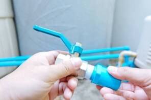
A typical Stop Valve consists of a body, stem, disc or ball, seat, seals, and handle. On a conventional Multi-Turn Stop Valve, turning the handle moves the stem and internal disc gradually toward or away from the seat, changing the flow area. Fully pressing the disc against the seat shuts off the flow. A Quarter-Turn Stop Valve normally opens or closes by rotating a ball or similar closure element approximately 90°.

Stop Valve Internal Section View
2) What Is the Difference Between a Stop Valve, Angle Valve, and Shut-off Valve?
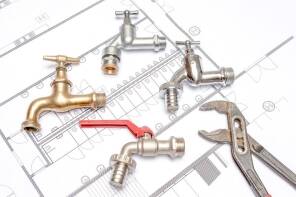
Any valve used to stop a medium can be called a Shut-off Valve. In residential plumbing, Stop Valve usually refers to a small shutoff valve installed upstream of terminal equipment, while Angle Valve / Angle Stop further specifies a 90° inlet-to-outlet configuration.
For example, when the pipe projects from a wall and the flexible hose runs upward to a faucet, an Angle Stop is commonly used. When the pipe rises from the floor and aligns generally with the equipment connection, a Straight Stop can be used. The main difference between a Straight Stop and an Angle Stop is the flow direction.
2. What Are the Main Types of Stop Valves?
Stop Valves are commonly classified in two ways: by the flow path through the body and by the opening/closing mechanism.
1) Straight Stop Valve
The inlet and outlet of a Straight Stop are essentially in line, so the water does not make a 90° turn inside the valve body. This design suits installations where the supply pipe and equipment hose run in generally the same direction.
Straight Stop vs Angle Stop
2) Multi-Turn Stop Valve
A conventional Multi-Turn Stop Valve normally requires several handle rotations to fully open or close. The design is mature and widely used. After long periods without operation, aging internal seals, scale buildup, or stem corrosion may cause incomplete shutoff or a sticking handle.
3) Quarter-Turn Stop Valve (90° Quick-Opening Stop Valve)
A Quarter-Turn valve generally requires only about 90° of rotation for full opening or closing. Its position is easy to identify and the operating travel is short, making it suitable for terminal water supply points that require rapid shutoff.
3. Where Are Stop Valves Mainly Used?
Stop Valves are commonly used for Point-of-Use Shutoff to isolate individual fixtures or equipment. They are generally not used as main shutoff valves on primary supply lines.
1) Basin and Faucet Water Supply
A basin normally has one Stop Valve on the cold-water line and one on the hot-water line. When replacing a faucet or hose, or carrying out maintenance, only the relevant hot- and cold-water branches need to be shut off; the entire residence or floor supply can remain in service.
2) Toilet and Bathroom Fixture Water Supply
A toilet normally requires only one cold-water supply, so a single Stop Valve provides independent control.
3) Water Supply for Washing Machines, Dishwashers, and Other Equipment
Washing machines, dishwashers, and other water-using equipment also require independent shutoff, and their equipment-side connections may differ from standard faucet connections. For OEM equipment projects in particular, confirm the interface in this order: equipment connection → hose → Stop Valve Outlet → building water supply pipe. This approach reduces the need for additional adapters to match interfaces.
4. How Are Common Stop Valve Sizes Read?
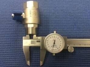
Understanding Stop Valve size designations helps identify the correct product specification and actual connection requirements. Start by checking the inlet and outlet sizes.
1) What Do Inlet Size and Outlet Size Mean?
The Inlet connects to the building water supply pipe, while the Outlet connects to the supply hose for a faucet, toilet, or other equipment.
2) What Does a 1/2″ × 3/8″ Stop Valve Mean?
It generally means a 1/2″ inlet and a 3/8″ outlet. However, this only defines the size combination and does not specify the complete connection type.
1/2″ × 3/8″ Stop Valve Size Designation
3) Common Stop Valve Inlet and Outlet Size Combinations
| Common Size | Typical Application |
| 1/2″ × 3/8″ | Terminal supply for faucets, toilets, etc. |
| 1/2″ × 1/2″ | For 1/2″ equipment connections |
| 3/8″ × 3/8″ | Small-size terminal connections |
| 1/2″ × Dual Outlet | Connects two devices to one supply line |
5. What Are the Common Stop Valve Inlet Connection Types?
Stop Valves with the same nominal sizes may use completely different Inlet Connections. Select the connection according to the piping installed on site.
1) Compression Connection
A Compression connection uses a nut, ferrule, and related components to form a mechanical joint and seal around the outside of the pipe. It is very common on copper terminal water lines. No soldering is required, but the pipe diameter, ferrule, nut, and valve connection must match.
2) Threaded Connection
A threaded connection must specify the exact thread standard; stating only “Threaded” does not fully define the interface. North American projects may use NPT, while other markets may use BSPP (G) or BSPT (R). A 1/2″ NPT thread is not the same as G1/2. OEM drawings can directly specify the thread standard, nominal size, and male/female form to avoid suppliers making assumptions based on market practice.
3) PEX / CPVC Connection
PEX and CPVC are different piping systems and require Stop Valves designed for the corresponding connection. For example, a 1/2″ CPVC × 3/8″ OD Compression valve uses a 1/2″ CPVC inlet connection and a 3/8″ Compression outlet connection.
4) Push-to-Connect
Push-to-Connect fittings connect directly to the pipe through an internal gripping mechanism and O-ring or similar components, reducing installation steps on site.
5) Which Connection Should Be Used for Different Supply Pipes?
First identify the site piping material, then select the corresponding connection:
| Site Supply Pipe | Common Connection Options |
| Copper | Compression / Sweat / Compatible Push-to-Connect |
| PEX | Corresponding PEX connection |
| CPVC | Corresponding CPVC connection |
| Threaded Pipe/Fitting | Corresponding NPT or BSP thread |
| Multiple Compatible Pipe Materials | Certified Push-to-Connect product |
Matching the valve directly to the site connection reduces the need for additional adapters. Every added adapter also adds another joint and another installation step.
Overview of Inlet Connection Types
6. How Do You Select a Stop Valve?
Select a Stop Valve according to installation conditions, operating requirements, and the service environment.
1) Straight Stop or Angle Stop?
Selection basis: the relative position of the pipe and equipment connection.
- Angle Stop: Use when water exits the wall and must turn toward equipment below (90° change in direction). Most fixture supply valves in North American residences are Angle Stops because the concealed female-threaded elbow in the wall is horizontal while the equipment connection is below.
- Straight Stop: Use when the pipe and equipment connection are in line and no change in direction is required, such as exposed piping, horizontal runs between equipment, or piping above ceilings.
2) Multi-Turn or Quarter-Turn?
| Decision Factor | Multi-Turn | Quarter-Turn |
| Operating Frequency | Locations operated infrequently; suitable for conventional maintenance replacement. After long periods without operation, check for stem sticking and seal aging. | Locations operated frequently; quick operation with clear valve position. |
| Safety Requirement | Acceptable where shutoff by multiple turns is suitable, although handwheel position may not clearly indicate valve status. | Use where open/closed status must be confirmed quickly. Handle position clearly indicates valve status, suitable for frequently serviced or public-use locations. |
| Flow Adjustment | Provides some flow-adjustment capability through gradual opening or closing. | Mainly for rapid full-open/full-close service; not suitable for precise flow control. |
| Water-Hammer Sensitivity | For water-hammer-sensitive systems; slower closing reduces the risk of instantaneous water hammer. | For systems requiring rapid shutoff; in high-pressure or long-pipe systems, consider water hammer caused by fast closure. |
| Budget | Limited budget | Adequate budget |
| New Project | — | Recommended (current mainstream option, long service life, convenient operation) |
| Maintenance Replacement | Match the existing type to avoid user confusion. | Upgrade replacement (recommended to improve operating experience). |
Multi-Turn vs Quarter-Turn Selection Chart
3) Determine the Inlet Connection from the Supply Pipe
a.Confirm the pipe material: copper, PEX, CPVC, or iron pipe?
b.Confirm the existing connection: is there a female-threaded elbow in the wall, a PEX stub-out, a copper stub-out, or another connection?
c.Select the matching inlet connection:
- Female-threaded elbow → NPT threaded inlet
- PEX stub-out → PEX crimp/expansion inlet or Push-to-Connect
- Copper stub-out → Sweat, Push-to-Connect, or Compression
- Uncertain / mixed piping materials → Push-to-Connect (universal compatibility)
d.Confirm the size: residential applications are almost always 1/2″; verify the actual size.
4) Determine the Outlet Size from the Equipment Hose
a. Check the connection specification of the equipment Supply Tube:
- Standard North American toilet / basin / kitchen faucet: 3/8″ OD compression nut → 3/8″ OD Compression outlet
- European faucet: 3/8″ or 1/2″ female-threaded nut → corresponding male-threaded outlet
- Water purifier / ice maker: 1/4″ OD → 1/4″ Compression outlet
- Water heater: normally 1/2″ or 3/4″ → corresponding outlet size
b. For a new project where the hose has not yet been purchased, use a 3/8″ OD outlet to North American practice and match it with a standard 3/8″ supply hose.
5) Confirm Brass Material and Service Requirements
Material checklist:
a. Valve body material: Give priority to Lead-Free Brass (lead ≤0.25%) compliant with the NSF/ANSI 61 drinking-water safety standard. Conventional leaded brass containing 1–3% lead does not comply with North American drinking-water regulations and must not be used in potable-water contact applications.
b. Cartridge / closure element: A Quarter-Turn valve may use a ceramic cartridge or ball closure depending on the product design. Verify operating life, pressure resistance, temperature resistance, and cycle-test data. Some high-quality products provide hundreds of thousands of cycles or more; use the manufacturer’s test report or applicable product standard for the actual value.
c. Stem packing: The stem should have an adjustable Packing Gland, using a hex nut or two bolts, so aging packing can be tightened or replaced. Low-cost products may use a simple rubber O-ring that cannot be adjusted and has a shorter service life.
d. Surface finish: Chrome (bright chrome, most common and durable), Brushed Nickel (modern appearance), Matte Black (protect against impact and paint damage), and Original Brass (natural brass that oxidizes and develops a patina).
Materials and Surface Finishes
a. Certification requirements:
- United States / Canada: NSF/ANSI 61 (drinking-water extraction) + UPC/cUPC (IAPMO, performance and safety)
- California and other lead-free jurisdictions: + AB 1953 compliance (NSF/ANSI 372 lead-free certification)
- United Kingdom: WRAS
- Germany / European Union: DVGW + CE
- Australia: WaterMark
b. Special service-environment requirements:
- Hot water / water heater: EPDM seals, temperature resistance ≥90°C
- Coastal areas / high-chloride water: 316 stainless steel or DZR dezincification-resistant brass
- High-rise buildings / unstable water pressure: reinforced valve body, pressure rating ≥2.5 MPa
7. What Are the Advantages and Limitations of Stop Valves?
Understanding where a Stop Valve is suitable helps determine whether it fits a specific point-of-use water supply system. Its main advantages are local control and convenient routine maintenance.
1) Main Advantages of Stop Valves
a. Local isolation without affecting the whole system: Toilets, basins, kitchens, water heaters, and equipment branches can be controlled separately. If one fixture leaks, close only its Stop Valve; there is no need to shut off the whole-house main valve or drain the entire system. In rental properties and commercial buildings, maintenance in one room does not interrupt operation in other units.
b. Reliable sealing and shutoff: The forced compression of the rubber washer in a Multi-Turn valve and the ceramic / ball seal in a Quarter-Turn valve can both provide reliable shutoff.
c. Simple construction and easy maintenance: The body, bonnet, stem, and cartridge can be removed and replaced. A Multi-Turn valve may only require a new rubber washer, while a Quarter-Turn valve can use a replacement cartridge without replacing the entire valve body.
d. Multiple connection options for all common pipe materials: NPT threaded, Compression, PEX crimp, CPVC solvent connection, Push-to-Connect, and Sweat connections cover the common residential water-supply piping materials used in North America.
e. Low cost and suitable for volume projects: The cost is lower than a ball valve or gate valve of the same size, making Stop Valves suitable for large fit-out projects.
f. Clear Quarter-Turn position indication: Handle parallel to the pipe = open; perpendicular = closed. The status is visible at a glance and avoids maintenance incidents where a Multi-Turn valve is assumed to be closed but is not fully shut.
2) What Are the Limitations of Stop Valves?
a. Relatively high flow resistance: Flow through an Angle Stop makes two 90° turns, producing a higher local resistance coefficient and noticeable pressure loss even when fully open. It is not suitable for Main Supply Lines or low-pressure systems. Use a gate valve or ball valve for the building main shutoff instead of a Stop Valve.
b. Multi-Turn valves operate slowly and do not clearly show position: They require 4–8 turns and are slower than Quarter-Turn valves for emergency shutoff. With a concealed-stem design, the handwheel position does not directly indicate valve status, increasing the risk of operating errors.
c. Some models have installation-direction requirements: Multi-Turn Stop Valves generally require flow to enter below the disc and exit above it. Reverse installation may prevent tight shutoff and place abnormal loads on the stem. The angle configuration of an Angle Stop inherently defines its direction, but the inlet and outlet must still be verified during installation. Quarter-Turn ceramic / ball designs normally have no strict flow-direction requirement.
d. Not suitable for media containing large amounts of particles: Particles can lodge between sealing surfaces, causing incomplete shutoff and scratching the seal faces. Stop Valves are intended only for clean tap water, hot water, and gas; they are not suitable for wastewater, irrigation water containing sediment, or viscous fluids.
e. Stem packing is a weak point: The Packing is one of the most common leakage points on a Stop Valve and requires periodic inspection and maintenance by tightening or replacing the packing.
f. Rapid Quarter-Turn closure may cause water hammer: In high-rise, high-pressure systems, rapidly closing a 90° valve may cause Water Hammer, resulting in pipe vibration, noise, or even loose joints. For water-hammer-sensitive systems, use a Multi-Turn valve or install a Water Hammer Arrester.
8. Common Stop Valve Problems
Problem 1: Leakage at the Stem
Symptom: Water seeps from below the handwheel, at the stem-to-body connection, and drips down the stem or valve body. Causes:
Aged packing: Packing, such as graphite or PTFE rings, surrounds the stem where it passes through the valve body and is compressed by the packing gland to form a seal. After several years, the packing can lose elasticity or wear against the stem and begin to leak.
Loose packing gland: Long-term vibration and thermal expansion/contraction can loosen the gland nut so it no longer compresses the packing sufficiently. Tightening the gland can correct this condition.
Damaged stem: Sand can scratch the stem surface, corrosion can attack it, or a wrench can score it during installation. Once grooves form, tightening the packing will not seal them and water can leak along the grooves. Replacing only the packing will not solve this condition; replace the stem or the complete valve.
Incorrect packing material: Standard rubber packing used on hot-water or gas service can quickly harden and crack at high temperature.
Corrective action: First, use a wrench to tighten the packing gland evenly, alternating between both sides where applicable. If the leak stops, the issue is resolved. If leakage continues after tightening, or the stem becomes difficult to turn, the packing has aged and needs replacement. Before replacing the packing, close the upstream and downstream valves, drain and depressurize the line, remove the handwheel and gland, remove the old packing, install new packing rings, and retighten. If the stem is grooved, replace the valve directly.
Problem 2: Valve Does Not Shut Off Completely and Still Leaks
Symptom: Water continues to flow downstream after the handwheel is fully tightened, or the pressure gauge reading slowly drops. Causes:
Incorrect flow direction: Many conventional Stop Valves require flow to enter below the disc and exit above it. If installed backward, water enters from above and pressure pushes the disc upward during closing, preventing the handwheel from fully seating it. Check the arrow on the valve body; it must point in the direction of flow.
Debris on the sealing surfaces: Welding slag, rust, or scale from the pipe can become trapped between the disc and seat and prevent full contact. This is especially common when new piping has not been properly flushed. Cycle the valve several times to flush out debris, or dismantle and clean it.
Damaged sealing surfaces: Over time, particles can scratch a soft rubber seal, the seal can age and deform, or erosion can form grooves in a metal sealing surface. Wear occurs faster in hot water and water containing sand. Replace the rubber washer for a soft seal or the seat for a hard seal.
Worn stem threads: Excessive operating force or long-term reverse installation can wear the threads until the handwheel reaches its limit before the disc is fully seated. Replace the stem or complete valve.
Not fully closed: On some Multi-Turn Stop Valves, the disc position cannot be determined directly from the handwheel. The valve may appear fully closed while the disc has not completely compressed against the seat. When closing, once resistance increases noticeably, turn the handwheel another quarter turn; do not judge closure only by the number of turns.
Problem 3: Handwheel Will Not Turn or Valve Operation Is Stiff
Symptom: The handwheel cannot be moved, or it turns with high and uneven resistance. Causes:
Rust or scale on the stem threads: On Stop Valves left unused for long periods, moisture can collect around the stem threads, causing corrosion or scale that locks the threads. This is especially common in heating systems. When a valve remains closed during summer, water around the stem threads evaporates and concentrates minerals, which can seize the threads.
Packing compressed too tightly: After repairing a leak, overtightening the packing gland can clamp the stem. A typical sign is that the valve suddenly becomes difficult to turn immediately after packing replacement. Loosen the gland slightly.
Incorrect flow direction: Long-term reverse installation can place side load on the stem, deforming the threads and causing binding.
Bent stem: Side impact during installation or maintenance can bend the stem, causing eccentric rotation and binding.
Frozen valve: Residual water can freeze inside the valve and completely lock the handwheel. Do not force it. Ice expansion may already have cracked the body. Allow it to thaw naturally and then inspect for cracks.
Corrective action: Apply rust penetrant to corroded or scaled threads, wait about half an hour, and try to turn the valve slowly. If it still will not move, close the upstream and downstream valves, drain the line, and replace the complete valve. Do not use an extension pipe to force the handwheel; the stem can break or the body can crack.
Problem 4: Leakage at the Valve-to-Pipe Connection
Symptom: Water seeps from the threaded connection between the Stop Valve and pipe. Causes:
PTFE tape wrapped in the wrong direction or with too few turns: A male-threaded valve screws in clockwise, so the PTFE tape should be wrapped counterclockwise around the thread. If wrapped in the wrong direction, the tape can loosen during assembly; too few wraps may not seal.
Insufficient tightening: The connection was not tightened enough during installation, and long-term pressure pulsation gradually loosened the joint.
Incorrect thread standard: NPT threaded into G thread, or vice versa, will not seal because the thread forms do not match.
Compression joint overtightened or pipe cut out of square: An over-compressed ferrule, angled pipe cut, or burrs can prevent proper sealing.
Porosity in the valve body: Low-cost cast-brass bodies may contain small casting pores that leak under water pressure. Forged brass generally has fewer typical casting pinholes.
Common Stop Valve Failure Cases
Problem 5: Insufficient Flow or Excessive Pressure Loss
Symptom: Downstream flow remains noticeably low with the Stop Valve fully open, or there is a large pressure difference across the valve. Causes:
High inherent valve resistance: The internal flow path has multiple changes in direction, so installing a Stop Valve on a main water line can cause significant pressure loss. Use a gate valve or ball valve for the building main shutoff, not a Stop Valve.
Disc not fully lifted: A concealed stem does not show disc position, so the valve may appear fully open while the disc still obstructs part of the passage. Fully close and reopen the valve, then back the handwheel off a quarter turn after reaching the fully open position to confirm full opening.
Valve size too small: Using a 1/2″ Stop Valve on a 3/4″ line creates excessive throttling.
Internal scale blockage: Scale can accumulate on the seat and flow passage over time, reducing the effective bore. This is common in hard-water areas and heating systems. Dismantle and clean the valve or replace it.
Problem 6: Radiator Does Not Heat; the Stop Valve May Be the Cause
Symptom: One radiator remains cold or is hot on one side and cool on the other. Causes:
Stop Valve not fully open: During fit-out or commissioning, workers may have throttled the valve and later forgotten to reopen it. Check the handwheel and fully open the valve.
Incorrect flow direction: On Stop Valves designed for flow to enter below the disc and exit above it, reverse installation restricts flow. Insufficient radiator flow then reduces heating performance.
Detached disc: The connection between the stem and disc has separated. The handwheel turns, but the disc does not move, leaving the valve partly open or closed. Dismantle and reconnect the components or replace the valve.
Internal scale blockage: If a heating system is not cleaned for a long period, scale and rust can accumulate around the seat and reduce flow. Clean or replace the valve.
9. Conclusion
Stop Valve performance depends on how well the product specification matches the complete installation system. A suitable Stop Valve must provide reliable connections, an appropriate operating method, compatible materials, and stable long-term service.
Plumberstar can provide Stop Valves and other plumbing valve products for residential, commercial, and OEM projects. Based on project requirements, we can assist with matching sizes, connection types, materials, structures, and relevant certifications to reduce interface mismatches and later maintenance issues. If you are developing or sourcing Stop Valve products, contact Plumberstar for a solution better suited to the specific application.